INTERNAL PANEL
3 | 8 | 9 | 12 |
4
5
6
7 | 10 | 13 | 11 |
INTERNAL PANEL FEATURES
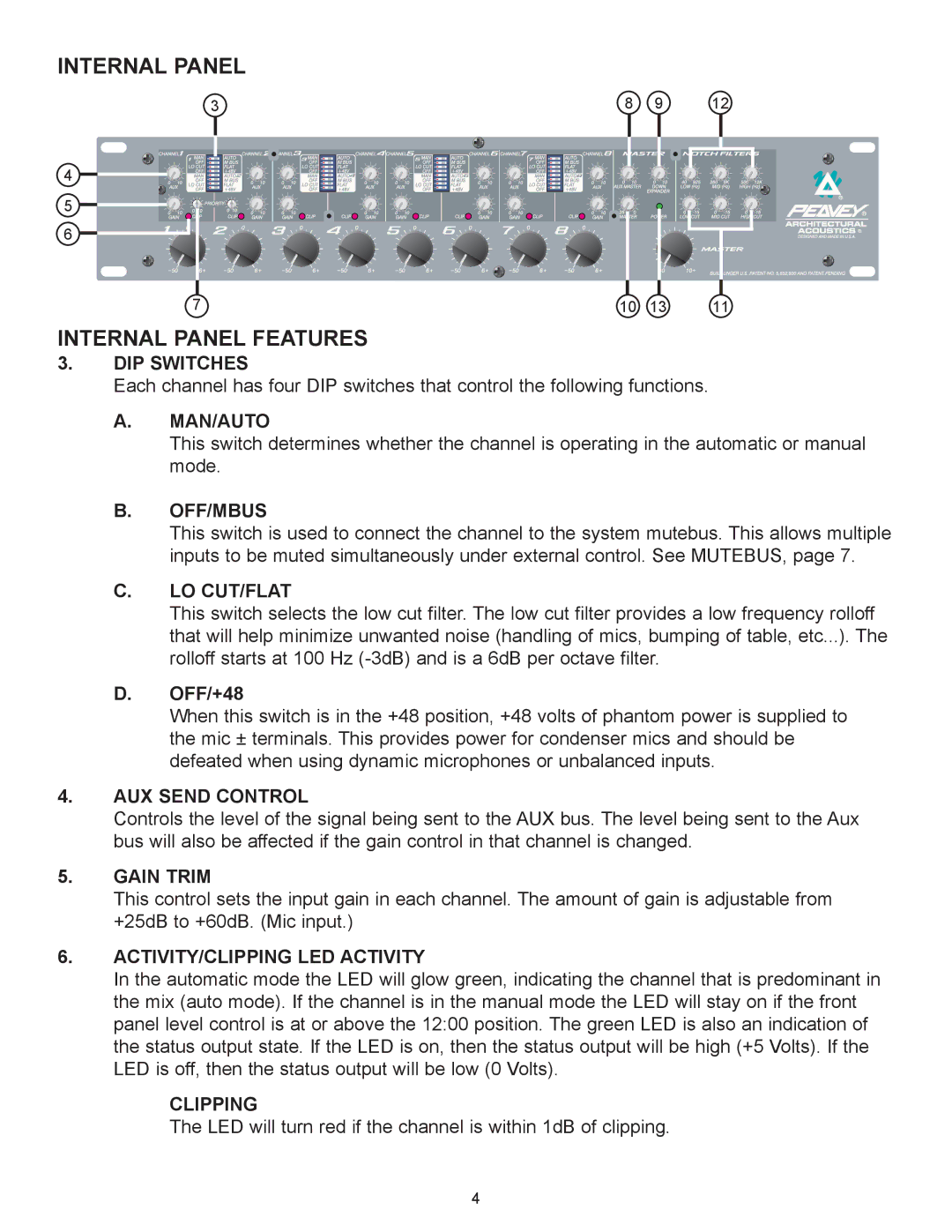
3.DIP SWITCHES
Each channel has four DIP switches that control the following functions.
A.MAN/AUTO
This switch determines whether the channel is operating in the automatic or manual mode.
B.OFF/MBUS
This switch is used to connect the channel to the system mutebus. This allows multiple inputs to be muted simultaneously under external control. See MUTEBUS, page 7.
C.LO CUT/FLAT
This switch selects the low cut filter. The low cut filter provides a low frequency rolloff that will help minimize unwanted noise (handling of mics, bumping of table, etc...). The rolloff starts at 100 Hz
D.OFF/+48
When this switch is in the +48 position, +48 volts of phantom power is supplied to the mic ± terminals. This provides power for condenser mics and should be defeated when using dynamic microphones or unbalanced inputs.
4.AUX SEND CONTROL
Controls the level of the signal being sent to the AUX bus. The level being sent to the Aux bus will also be affected if the gain control in that channel is changed.
5.GAIN TRIM
This control sets the input gain in each channel. The amount of gain is adjustable from +25dB to +60dB. (Mic input.)
6.ACTIVITY/CLIPPING LED ACTIVITY
In the automatic mode the LED will glow green, indicating the channel that is predominant in the mix (auto mode). If the channel is in the manual mode the LED will stay on if the front panel level control is at or above the 12:00 position. The green LED is also an indication of the status output state. If the LED is on, then the status output will be high (+5 Volts). If the LED is off, then the status output will be low (0 Volts).
CLIPPING
The LED will turn red if the channel is within 1dB of clipping.
4
