Session 300 Rear Panel
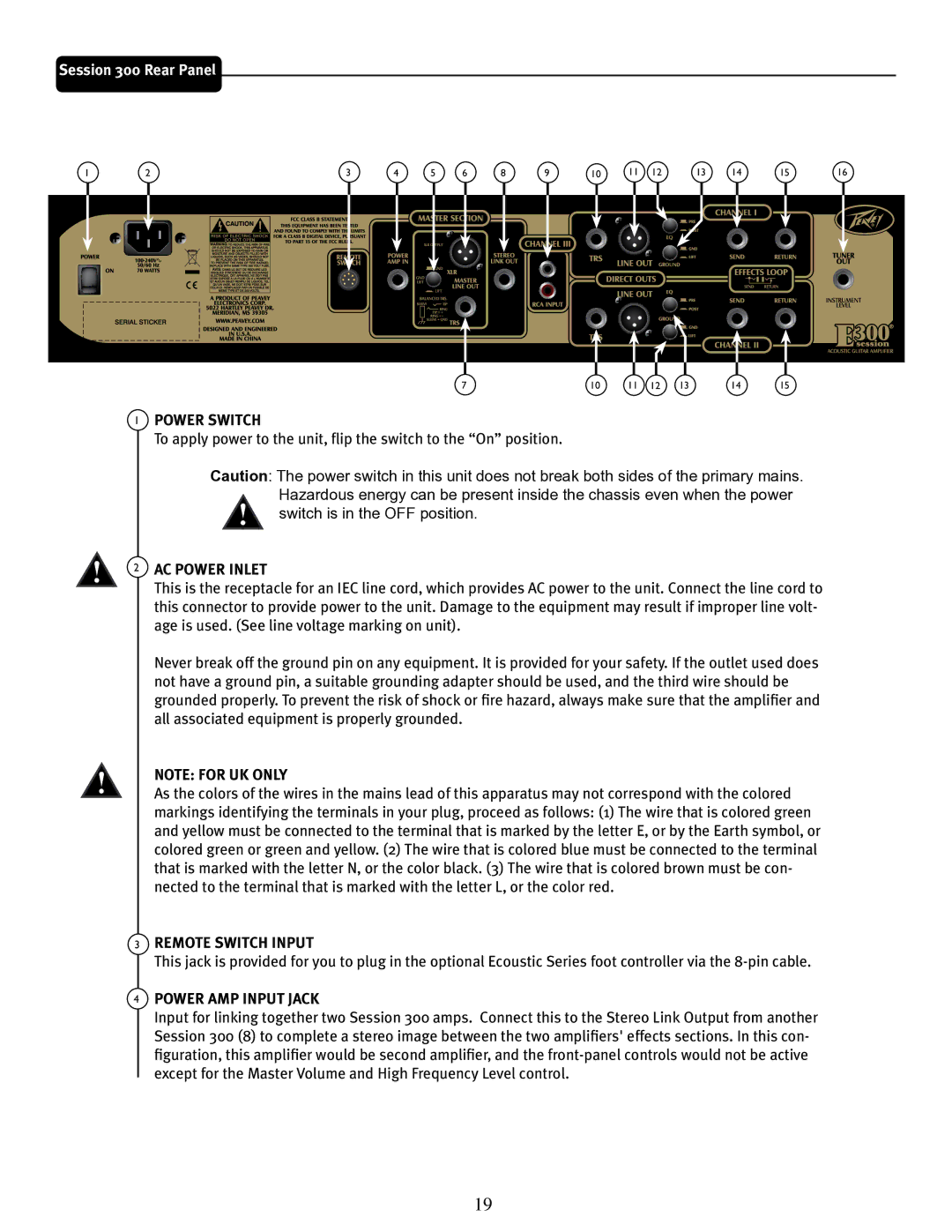
1 | 2 | 3 | 4 | 5 | 6 | 8 | 9 | 10 | 11 | 12 | 13 | 14 | 15 | 16 |
7 | 10 | 11 | 12 | 13 | 14 | 15 |
1POWER SWITCH
To apply power to the unit, flip the switch to the “On” position.
Caution: The power switch in this unit does not break both sides of the primary mains. Hazardous energy can be present inside the chassis even when the power ![]() switch is in the OFF position.
switch is in the OFF position.
2 AC POWER INLET
This is the receptacle for an IEC line cord, which provides AC power to the unit. Connect the line cord to this connector to provide power to the unit. Damage to the equipment may result if improper line volt- age is used. (See line voltage marking on unit).
Never break off the ground pin on any equipment. It is provided for your safety. If the outlet used does not have a ground pin, a suitable grounding adapter should be used, and the third wire should be grounded properly. To prevent the risk of shock or fire hazard, always make sure that the amplifier and all associated equipment is properly grounded.
NOTE: FOR UK ONLY
As the colors of the wires in the mains lead of this apparatus may not correspond with the colored markings identifying the terminals in your plug, proceed as follows: (1) The wire that is colored green and yellow must be connected to the terminal that is marked by the letter E, or by the Earth symbol, or colored green or green and yellow. (2) The wire that is colored blue must be connected to the terminal that is marked with the letter N, or the color black. (3) The wire that is colored brown must be con- nected to the terminal that is marked with the letter L, or the color red.
3REMOTE SWITCH INPUT
This jack is provided for you to plug in the optional Ecoustic Series foot controller via the
4POWER AMP INPUT JACK
Input for linking together two Session 300 amps. Connect this to the Stereo Link Output from another Session 300 (8) to complete a stereo image between the two amplifiers' effects sections. In this con- figuration, this amplifier would be second amplifier, and the
19