F R O N T PA N E L
6 | 5 | 2 | 1 |
7 4 3
|
|
|
|
|
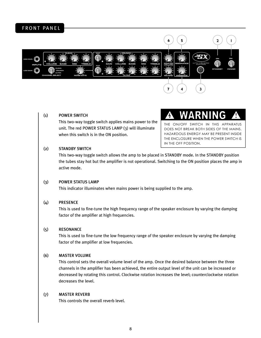
(1) | POWER SWITCH | WARNING | ||
|
|
| ||
| This |
|
|
|
| THE ON/OFF SWITCH IN THIS APPARATUS | |||
| unit. The red POWER STATUS LAMP (3) will illuminate | |||
| DOES NOT BREAK BOTH SIDES OF THE MAINS. | |||
| when this switch is in the ON position. | HAZARDOUS ENERGY MAY BE PRESENT INSIDE | ||
|
| THE ENCLOSURE WHEN THE POWER SWITCH IS | ||
|
| IN THE OFF POSITION. | ||
(2)STANDBY SWITCH
This
(3)POWER STATUS LAMP
This indicator illuminates when mains power is being supplied to the amp.
(4)PRESENCE
This is used to
(5)RESONANCE
This is used to
(6)MASTER VOLUME
This control sets the overall volume level of the amp. Once the desired balance between the three channels in the amplifier has been achieved, the entire output level of the unit can be increased or decreased by rotating this control. Clockwise rotation increases the level; counterclockwise rotation decreases the level.
(7)MASTER REVERB
This controls the overall reverb level.
8
