Installation to Concrete Ceilings or Concrete/Cinder Block Walls
![]() WARNING
WARNING
•When installing Peerless wall mounts on cinder block, verify that you have a minimum of
•Concrete must be 2000 psi density minimum. Lighter density concrete may not hold concrete anchor.
•Installer must verify that the supporting surface will safely support the combined load of the equipment and all attached hardware and components.
2 | NOTE: Wall installation with models EXC, | CEILING |
|
| |
and |
|
| |||
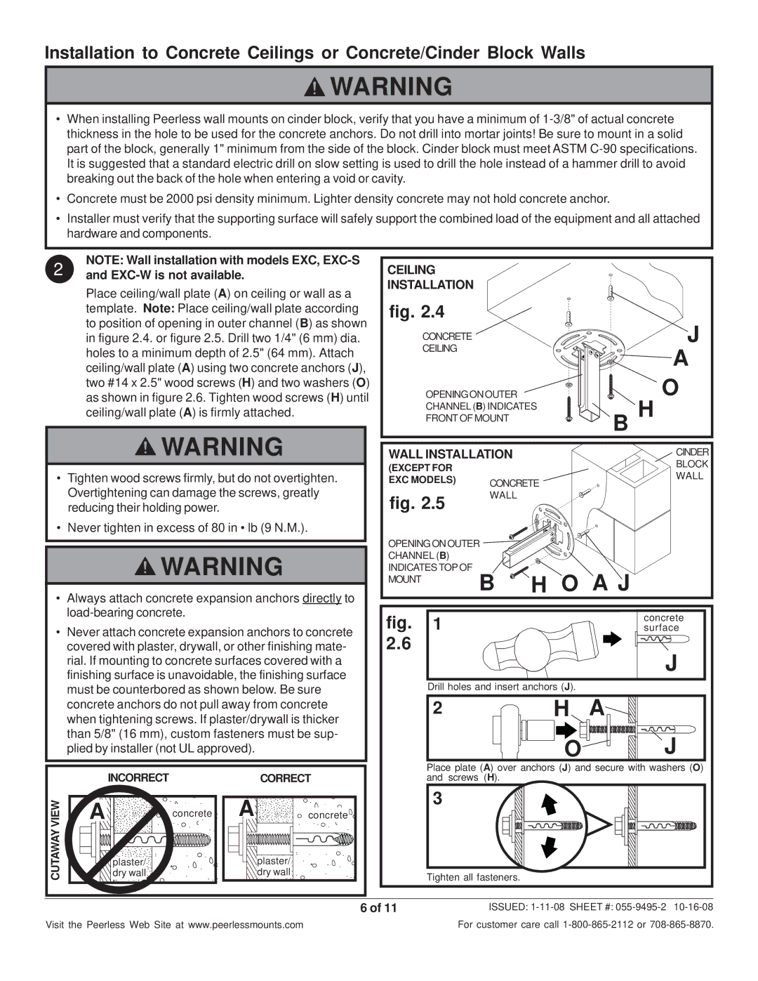
| Place ceiling/wall plate (A) on ceiling or wall as a | INSTALLATION |
|
| |
| fig. 2.4 |
|
| ||
| template. Note: Place ceiling/wall plate according |
|
| ||
| to position of opening in outer channel (B) as shown |
|
| J | |
| in figure 2.4. or figure 2.5. Drill two 1/4" (6 mm) dia. | CONCRETE |
| ||
| holes to a minimum depth of 2.5" (64 mm). Attach | CEILING |
| A | |
| ceiling/wall plate (A) using two concrete anchors (J), |
|
| ||
| two #14 x 2.5" wood screws (H) and two washers (O) | OPENING ON OUTER | O | ||
| as shown in figure 2.6. Tighten wood screws (H) until | ||||
| ceiling/wall plate (A) is firmly attached. | CHANNEL (B) INDICATES | B H | ||
| FRONT OF MOUNT | ||||
| WARNING | WALL INSTALLATION | CINDER | ||
|
| (EXCEPT FOR |
| BLOCK | |
• Tighten wood screws firmly, but do not overtighten. |
| WALL | |||
EXC MODELS) | CONCRETE | ||||
| |||||
| Overtightening can damage the screws, greatly | fig. 2.5 | WALL |
| |
| reducing their holding power. |
|
| ||
• Never tighten in excess of 80 in • lb (9 N.M.).
|
| OPENING ON OUTER |
|
| |
| WARNING | CHANNEL (B) |
|
| |
| MOUNT |
|
|
| |
|
| INDICATES TOP OF | H O | A J | |
• | Always attach concrete expansion anchors directly to |
| B | ||
|
|
|
| ||
| fig. | 1 |
| concrete | |
• Never attach concrete expansion anchors to concrete |
| surface | |||
| covered with plaster, drywall, or other finishing mate- | 2.6 |
|
| J |
| rial. If mounting to concrete surfaces covered with a |
|
|
| |
| finishing surface is unavoidable, the finishing surface |
| Drill holes and insert anchors (J). | ||
| must be counterbored as shown below. Be sure |
| A | ||
| concrete anchors do not pull away from concrete |
| 2 | H | |
| when tightening screws. If plaster/drywall is thicker |
| |||
| than 5/8" (16 mm), custom fasteners must be sup- |
|
| O | J |
| plied by installer (not UL approved). |
|
| ||
| INCORRECT |
|
| CORRECT | Place plate (A) over anchors (J) and secure with washers (O) | |
|
|
| and screws (H). |
| ||
VIEW | A | concrete | A | concrete | 3 |
|
|
| |||||
CUTAWAY | plaster/ |
|
| plaster/ |
|
|
dry wall |
|
| dry wall | Tighten all fasteners. |
| |
|
|
|
| 6 of 11 | ISSUED: | |
Visit the Peerless Web Site at www.peerlessmounts.com | For customer care call | |||||