Installation to Wood Stud Wall
![]() WARNING
WARNING
•Installer must verify that the supporting surface will safely support the combined load of the equipment and all attached hardware and components.
•Tighten wood screws so that wall plate is firmly attached, but do not overtighten. Overtightening can damage the screws, greatly reducing their holding power.
•Never tighten in excess of 80 in. • lb (9 N.M.).
•Make sure that mounting screws are anchored into the center of the stud. The use of an "edge to edge" stud finder is highly recommended.
•Hardware provided is for attachment of mount through standard thickness drywall or plaster into wood studs. Install- ers are responsible to provide hardware for other types of mounting situations.
1 |
|
| |
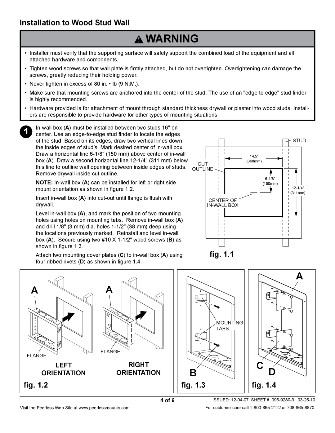
center. Use an |
|
| |
| of the stud. Based on its edges, draw two vertical lines down |
| STUD |
| the inside edges of stud’s. Mark desired center of |
|
|
| Draw a horizontal line |
| 14.5" |
| box (A). Draw a second horizontal line | cut | (368mm) |
| this line to outline wall opening between inside edges of studs. |
| |
| outline |
| |
| Remove drywall inside cut outline. |
| |
| NOTE: |
| |
|
| (150mm) | |
| mount orientation as shown in figure 1.2. |
| |
| Insert |
| (311mm) |
| center of |
| |
| drywall. |
| |
| Level |
|
|
| holes using holes on mounting tabs. Remove |
|
|
| and drill 1/8" (3 mm) dia. holes |
|
|
| the locations previously marked. Reinstall and level |
|
|
| box (A). Secure using two #10 X |
|
|
| shown in figure 1.3. |
|
|
Attach two mounting cover plates (C) to | fig. 1.1 |
four ribbed rivets (D) as shown in figure 1.4. |
|
| A |
|
| A |
A |
|
|
| |
|
|
| MOUNTING |
|
|
|
| TABS |
|
flange | flange |
|
|
|
|
|
|
| |
LEFT | RIGHT | B | C D |
|
ORIENTATION | ORIENTATION |
| ||
fig. 1.2 |
| fig. 1.3 | fig. 1.4 |
|
| 4 of 6 |
| ISSUED: |
Visit the Peerless Web Site at www.peerlessmounts.com | For customer care call |