Cable Management
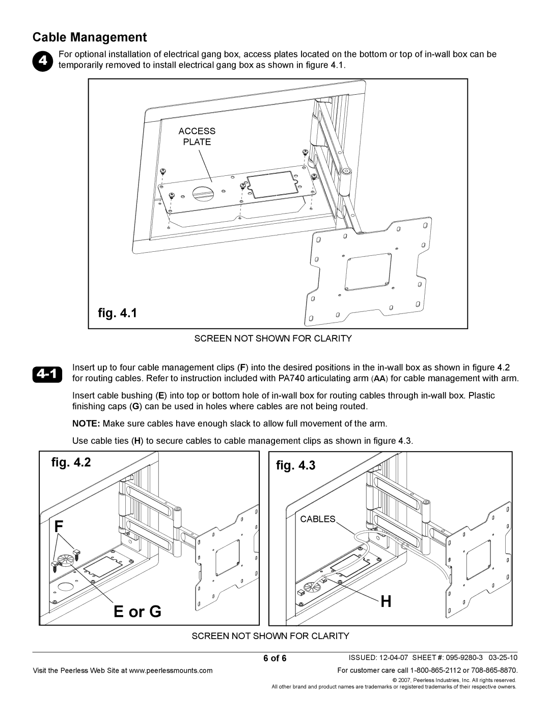
4 | For optional installation of electrical gang box, access plates located on the bottom or top of |
temporarily removed to install electrical gang box as shown in figure 4.1. |
Access |
plate |
fig. 4.1 |
screen not shown for clarity
Insert up to four cable management clips (F) into the desired positions in the | |
for routing cables. Refer to instruction included with PA740 articulating arm (AA) for cable management with arm. |
Insert cable bushing (E) into top or bottom hole of
Note: Make sure cables have enough slack to allow full movement of the arm.
Use cable ties (H) to secure cables to cable management clips as shown in figure 4.3.
fig. 4.2 |
F |
E or G |
fig. 4.3
cables
![]() H
H
screen not shown for clarity
6 of 6
Visit the Peerless Web Site at www.peerlessmounts.com
ISSUED:
© 2007, Peerless Industries, Inc. All rights reserved. All other brand and product names are trademarks or registered trademarks of their respective owners.