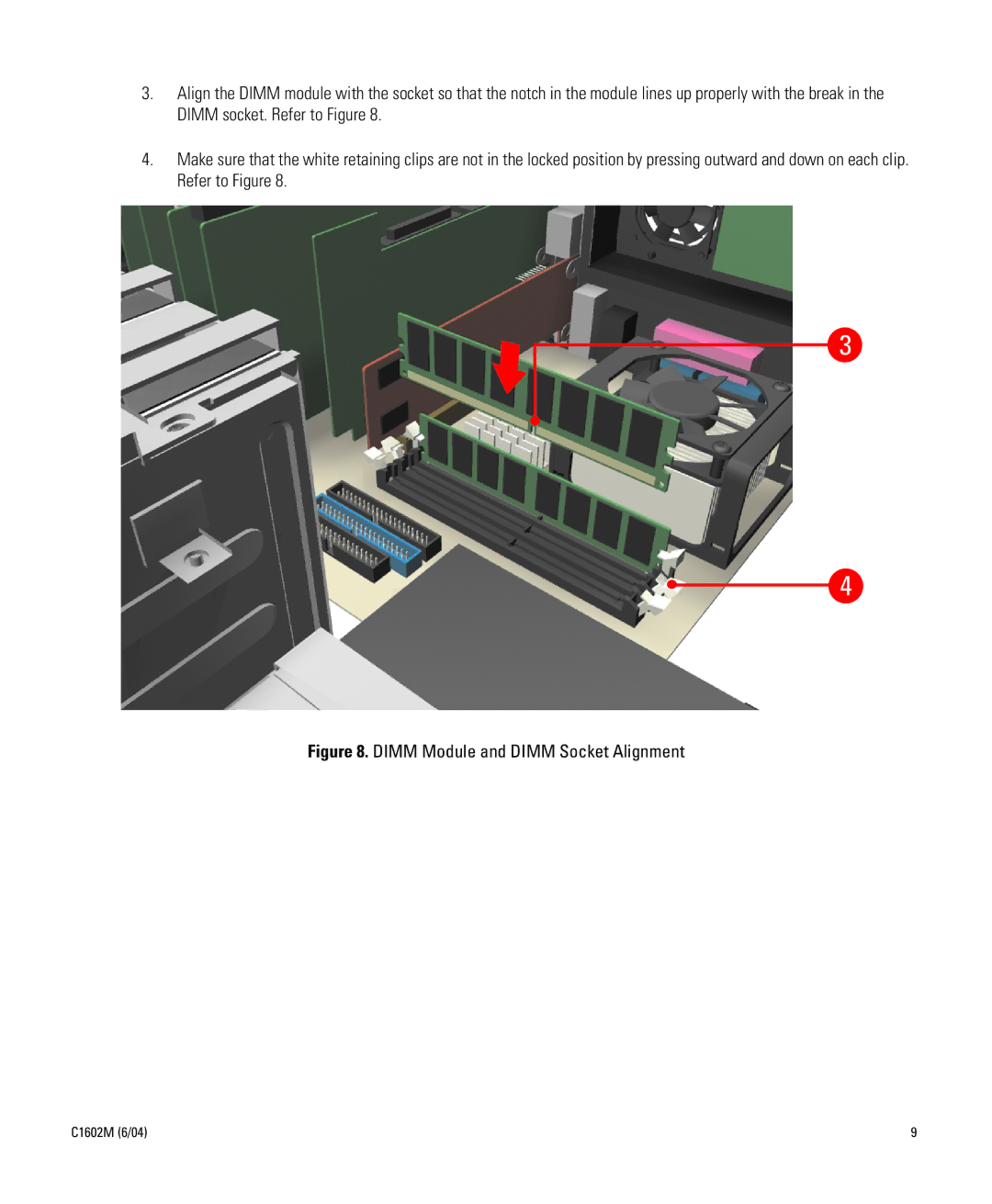
3.Align the DIMM module with the socket so that the notch in the module lines up properly with the break in the DIMM socket. Refer to Figure 8.
4.Make sure that the white retaining clips are not in the locked position by pressing outward and down on each clip. Refer to Figure 8.
3
4
Figure 8. DIMM Module and DIMM Socket Alignment
C1602M (6/04) | 9 |
