Camera Layout
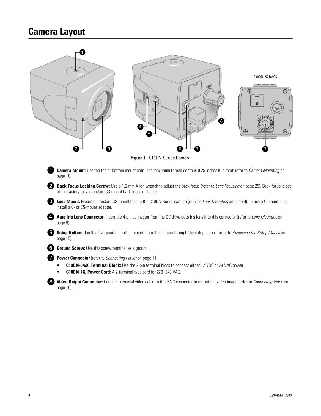
Figure 1. C10DN Series Camera
ìCamera Mount: Use the top or bottom mount hole. The maximum thread depth is 0.25 inches (6.4 mm); refer to Camera Mounting on page 10.
îBack Focus Locking Screw: Use a 1.5-mm Allen wrench to adjust the back focus (refer to Lens Focusing on page 25). Back focus is set at the factory for a standard CS-mount back focus distance.
ïLens Mount: Mount a standard CS-mount lens to the C10DN Series camera (refer to Lens Mounting on page 9). To use a C-mount lens, install a C- or CS-mount adapter.
ñAuto Iris Lens Connector: Insert the 4-pin connector from the DC drive auto iris lens into this connector (refer to Lens Mounting on page 9).
óSetup Button: Use this five-position button to configure the camera through the setup menus (refer to Accessing the Setup Menus on page 15).
rGround Screw: Use this screw terminal as a ground.
sPower Connector (refer to Connecting Power on page 11):
•C10DN-6/6X, Terminal Block: Use the 2-pin terminal block to connect either 12 VDC or 24 VAC power.
•C10DN-7X, Power Cord: A 2-terminal type cord for 220–240 VAC.
tVideo Output Connector: Connect a coaxial video cable to this BNC connector to output the video image (refer to Connecting Video on page 10).
8 |