3.Connect the network cable to the
NOTE: If the network has no Power over Ethernet (PoE), connect a 24 VAC Class 2 power supply to the 24 VAC power connector (refer to Figure 4).
1 | 2 | 3 | 4 | 5 | 6 | 7 | 8 |
|
|
|
|
|
| 1 |
|
|
| 8 |
|
|
| Pin | Function |
|
|
|
|
|
|
|
|
|
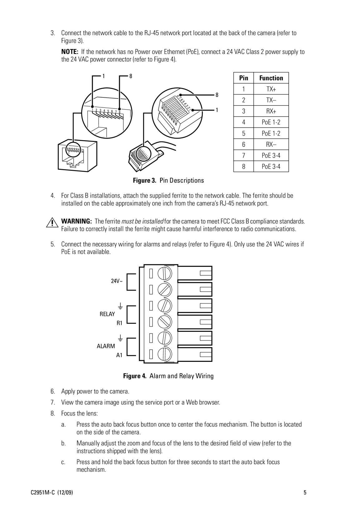
| 8 | 1 | TX+ |
|
|
|
|
|
|
|
| 7 |
|
|
| |
|
|
|
|
|
|
|
| 8 |
|
| 2 | TX– |
|
|
|
|
|
|
|
| 4 |
|
| ||
|
|
|
|
|
|
|
| 6 |
|
|
|
|
|
|
|
|
|
|
|
| 5 |
|
|
|
|
|
|
|
|
|
|
|
| 3 |
|
|
| |
1 | 2 |
| 4 | 5 | 6 | 7 | 8 |
| 2 | 1 | 3 | RX+ |
3 |
| 1 | ||||||||||
|
|
|
|
|
|
|
|
| ||||
|
|
|
|
|
|
|
|
|
|
| 4 | PoE |
|
|
|
|
|
|
|
|
|
|
| 5 | PoE |
|
|
|
|
|
|
| 8 |
|
|
| 6 | RX– |
|
|
|
|
|
|
|
|
|
|
|
| |
|
|
|
|
|
|
| 7 |
|
|
|
|
|
|
|
|
|
|
|
| 6 |
|
|
| 7 | PoE |
|
|
|
|
|
|
| 5 |
|
|
| ||
|
|
|
|
|
|
| 4 |
|
|
| ||
|
|
|
|
|
|
| 3 |
|
|
|
|
|
|
|
|
|
|
|
| 2 |
|
|
|
|
|
|
|
|
|
|
|
| 1 |
|
|
|
|
|
|
|
|
|
|
|
|
|
|
|
| 8 | PoE |
|
|
|
|
|
|
| Figure 3. | Pin Descriptions |
|
|
| |
4.For Class B installations, attach the supplied ferrite to the network cable. The ferrite should be installed on the cable approximately one inch from the camera’s
WARNING: The ferrite must be installed for the camera to meet FCC Class B compliance standards. Failure to correctly install the ferrite might cause harmful interference to radio communications.
5.Connect the necessary wiring for alarms and relays (refer to Figure 4). Only use the 24 VAC wires if PoE is not available.
24V~
RELAY
R1
ALARM
A1
Figure 4. Alarm and Relay Wiring
6.Apply power to the camera.
7.View the camera image using the service port or a Web browser.
8.Focus the lens:
a.Press the auto back focus button once to center the focus mechanism. The button is located on the side of the camera.
b.Manually adjust the zoom and focus of the lens to the desired field of view (refer to the instructions shipped with the lens).
c.Press and hold the back focus button for three seconds to start the auto back focus mechanism.
| 5 |