CAMERA ORIENTATION
At the factory, the camera module is configured for ceiling mounting. For wall mounting, you must change the camera orientation or the video image could be upside down or sideways.
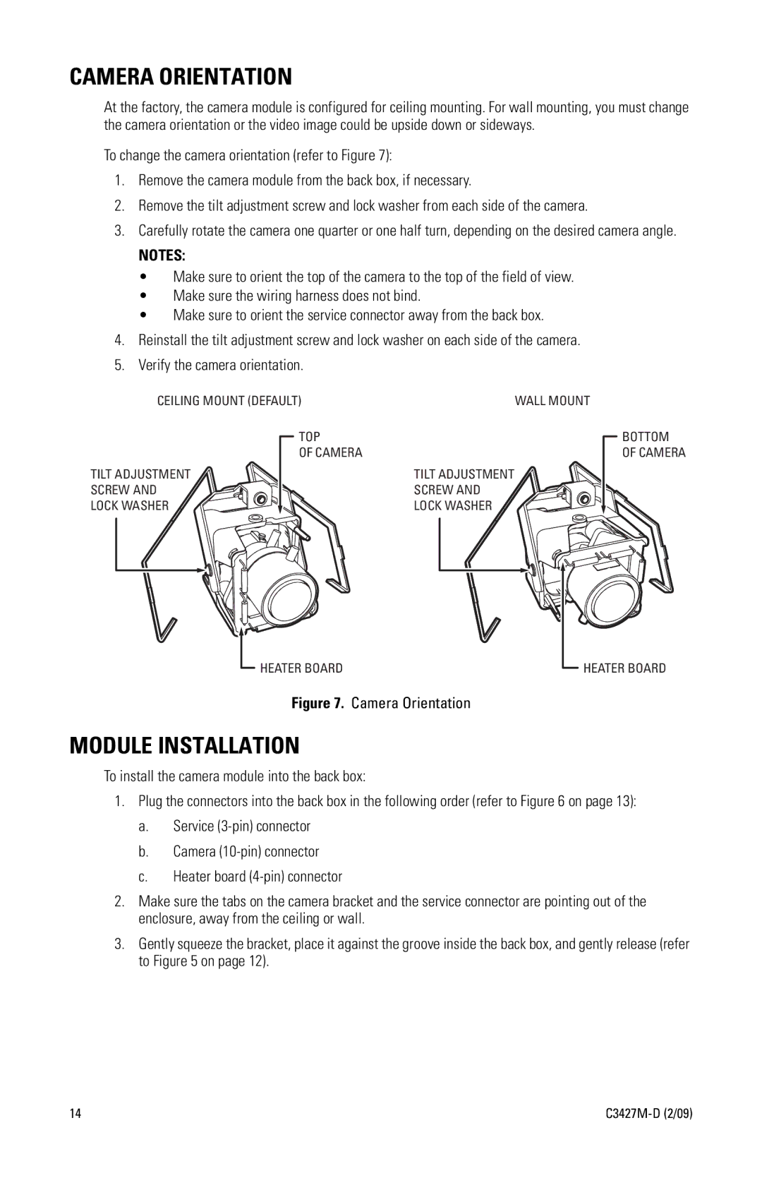
To change the camera orientation (refer to Figure 7):
1.Remove the camera module from the back box, if necessary.
2.Remove the tilt adjustment screw and lock washer from each side of the camera.
3.Carefully rotate the camera one quarter or one half turn, depending on the desired camera angle.
NOTES:
•Make sure to orient the top of the camera to the top of the field of view.
•Make sure the wiring harness does not bind.
•Make sure to orient the service connector away from the back box.
4.Reinstall the tilt adjustment screw and lock washer on each side of the camera.
5.Verify the camera orientation.
CEILING MOUNT (DEFAULT) | WALL MOUNT |
TOP |
|
OF CAMERA |
|
TILT ADJUSTMENT | TILT ADJUSTMENT |
SCREW AND | SCREW AND |
LOCK WASHER | LOCK WASHER |
BOTTOM OF CAMERA
HEATER BOARD
Figure 7. Camera Orientation
HEATER BOARD
MODULE INSTALLATION
To install the camera module into the back box:
1.Plug the connectors into the back box in the following order (refer to Figure 6 on page 13):
a.Service
b.Camera
c.Heater board
2.Make sure the tabs on the camera bracket and the service connector are pointing out of the enclosure, away from the ceiling or wall.
3.Gently squeeze the bracket, place it against the groove inside the back box, and gently release (refer to Figure 5 on page 12).
14 |