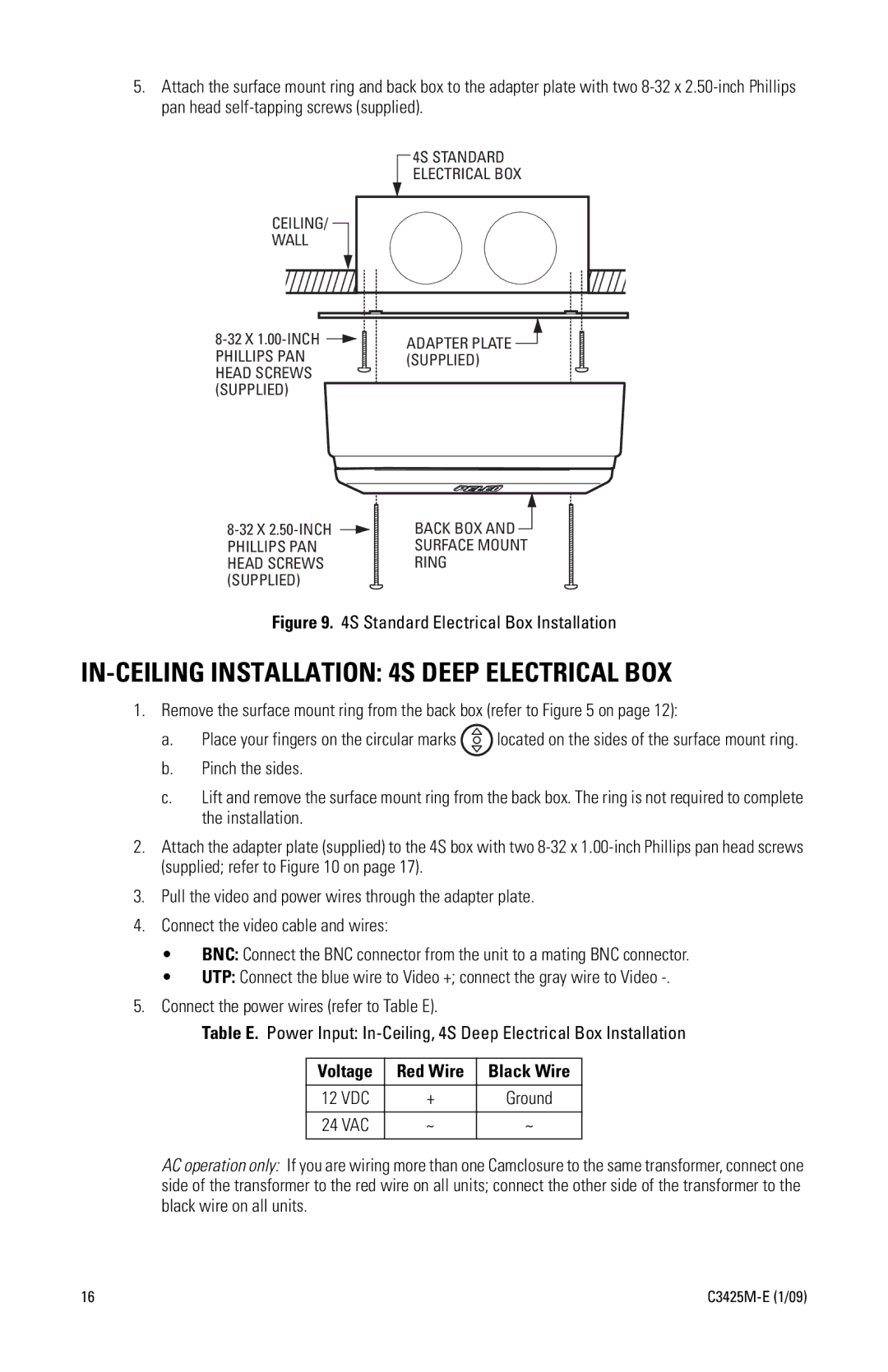
5.Attach the surface mount ring and back box to the adapter plate with two
4S STANDARD ELECTRICAL BOX
CEILING/ |
WALL |
ADAPTER PLATE ![]() (SUPPLIED)
(SUPPLIED)
BACK BOX AND ![]() SURFACE MOUNT RING
SURFACE MOUNT RING
Figure 9. 4S Standard Electrical Box Installation
IN-CEILING INSTALLATION: 4S DEEP ELECTRICAL BOX
1.Remove the surface mount ring from the back box (refer to Figure 5 on page 12):
a.Place your fingers on the circular marks ![]() located on the sides of the surface mount ring.
located on the sides of the surface mount ring.
b.Pinch the sides.
c.Lift and remove the surface mount ring from the back box. The ring is not required to complete the installation.
2.Attach the adapter plate (supplied) to the 4S box with two
3.Pull the video and power wires through the adapter plate.
4.Connect the video cable and wires:
• BNC: Connect the BNC connector from the unit to a mating BNC connector.
• UTP: Connect the blue wire to Video +; connect the gray wire to Video
5.Connect the power wires (refer to Table E).
Table E. Power Input:
Voltage | Red Wire | Black Wire |
|
|
|
12 VDC | + | Ground |
|
|
|
24 VAC | ~ | ~ |
|
|
|
AC operation only: If you are wiring more than one Camclosure to the same transformer, connect one side of the transformer to the red wire on all units; connect the other side of the transformer to the black wire on all units.
16 |