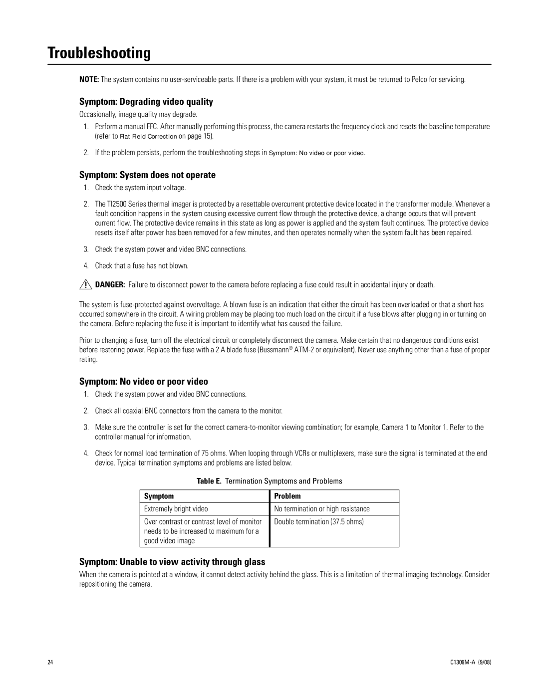
TI2550 specifications
The Pelco TI2550 is a state-of-the-art thermal imaging camera designed to enhance surveillance and security operations. It features advanced technology that enables users to detect and monitor heat signatures, making it an invaluable tool for various applications, including perimeter security, agricultural monitoring, and search and rescue missions.One of the standout features of the Pelco TI2550 is its high-resolution thermal sensor, which provides exceptional image quality even in the most challenging environmental conditions. With a resolution of 640 x 480 pixels, this camera captures fine details and allows operators to identify objects and individuals concealed by darkness, fog, smoke, or dust. This capability is crucial for nighttime surveillance or situations where visibility is compromised.
The TI2550 boasts a robust thermal sensitivity that can detect temperature differences as small as 50 mK, enabling it to identify subtle heat signatures. This level of sensitivity not only enhances detection capabilities but also ensures a high rate of false alarm reduction, making it a reliable choice for security personnel.
For versatility in deployment, the Pelco TI2550 offers a variety of lens options. Users can choose from multiple focal lengths to suit their specific needs, whether they require wide-angle views for expansive areas or narrow views for distant targets. Additionally, the camera is equipped with continuous zoom capabilities, allowing for real-time adjustments to the field of view.
The TI2550 integrates seamlessly with existing security systems, featuring standard video outputs such as Analog and IP formats. This compatibility ensures that the camera can be easily incorporated into both new and pre-existing surveillance infrastructures. Furthermore, it supports advanced video analytics that can help in automatic detections, such as alarming on unusual temperature variations.
With a ruggedized design, the Pelco TI2550 is built to withstand harsh environmental conditions. It is rated for both dust and water resistance, making it suitable for outdoor applications. Its ability to operate in extreme temperatures ensures dependable performance in diverse settings, from arctic cold to desert heat.
In conclusion, the Pelco TI2550 stands out in the realm of thermal imaging technology. With its high resolution, exceptional sensitivity, versatile lens options, and robust design, it serves as an essential tool for enhancing situational awareness and operational effectiveness in security and surveillance tasks. The integration of advanced analytics further positions the TI2550 as a formidable asset in modern security applications.

