Installation / Maintenance | 5 |
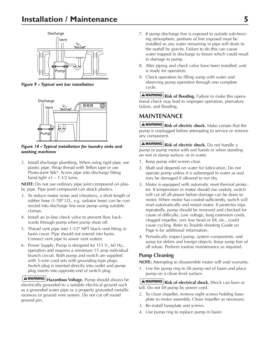
Discharge
Vent
Pump
Figure 9 – Typical wet bar installation
Discharge |
Vent |
Pump |
Figure 10 – Typical installation for laundry sinks and washing machines
2.Install discharge plumbing. When using rigid pipe, use plastic pipe. Wrap thread with Teflon tape or use
NOTE: Do not use ordinary pipe joint compound on plas- tic pipe. Pipe joint compound can attack plastics.
3.To reduce motor noise and vibrations, a short length of rubber hose
4.Install an
5.Thread vent pipe into
6.Power Supply: Pump is designed for 115 V., 60 Hz., operation and requires a minimum 15 amp individual branch circuit. Both pump and switch are supplied with
![]()
![]()
![]()
![]()
![]()
![]()
![]()
![]()
![]() Hazardous Voltage. Pump should always be electrically grounded to a suitable electrical ground such as a grounded water pipe or a properly grounded metallic raceway or ground wire system. Do not cut off round ground pin.
Hazardous Voltage. Pump should always be electrically grounded to a suitable electrical ground such as a grounded water pipe or a properly grounded metallic raceway or ground wire system. Do not cut off round ground pin.
7.If pump discharge line is exposed to outside
8.After piping and check valve have been installed, unit is ready for operation.
9.Check operation by filling sump with water and observing pump operation through one complete cycle.
![]()
![]()
![]()
![]()
![]()
![]()
![]()
![]()
![]() Risk of flooding. Failure to make this opera- tional check may lead to improper operation, premature failure, and flooding.
Risk of flooding. Failure to make this opera- tional check may lead to improper operation, premature failure, and flooding.
MAINTENANCE
![]()
![]()
![]()
![]()
![]()
![]()
![]()
![]()
![]() Risk of electric shock. Make certain that the pump is unplugged before attempting to service or remove any component.
Risk of electric shock. Make certain that the pump is unplugged before attempting to service or remove any component.
![]()
![]()
![]()
![]()
![]()
![]()
![]()
![]()
![]() Risk of electric shock. Do not handle a pump or pump motor with wet hands or when standing on wet or damp surface, or in water.
Risk of electric shock. Do not handle a pump or pump motor with wet hands or when standing on wet or damp surface, or in water.
1.Keep pump inlet screen clear.
2.Shaft seal depends on water for lubrication. Do not operate pump unless it is submerged in water as seal may be damaged if allowed to run dry.
3.Motor is equipped with automatic reset thermal protec- tor. If temperature in motor should rise unduly, switch will cut off all power before damage can be done to motor. When motor has cooled sufficiently, switch will reset automatically and restart motor. If protector trips repeatedly, pump should be removed and checked for cause of difficulty. Low voltage, long extension cords, clogged impeller, very low head or lift, etc., could cause cycling. Refer to Trouble shooting Guide on Page 6 for additional information.
4.Periodically inspect pump, system components, and sump for debris and foreign objects. Keep sump free of all refuse. Perform routine maintenance as required.
Pump Cleaning
NOTE: Attempting to disassemble motor will void warranty.
1.Use the pump ring to lift pump out of basin and place pump on a clean level surface.
![]()
![]()
![]()
![]()
![]()
![]()
![]()
![]()
![]() Risk of electrical shock. Shock can burn or kill. Do not lift pump by power cord.
Risk of electrical shock. Shock can burn or kill. Do not lift pump by power cord.
2.To clean impeller, remove eight screws holding base- plate to motor assembly. Clean impeller as necessary.
3.
4.Use pump ring to replace pump in basin.