ELECTRICAL SPECIFICATIONS
The following electrical specifications tabled below must not be exceeded.
ITEM | DESCRIPTION | LIMIT |
Input Voltage | Maximum Input AC Voltage | 125 VAC |
Input Current | Maximum Input Current | 5 AMPS (AC) |
Input current | Maximum Current for Single Relay | 5 AMPS (AC) |
Temperature | Minimum/Maximum Operating Temperature | 30° - 110° F |
Standby Current | Current with Relay OFF, LED ON | 50 mA (AC) Typical |
| Current with Relay OFF, LED OFF | 30 mA (AC) Typical |
Sensor Range | pH | 4.22 - 9.78 |
CONNECTING THE 110VAC POWER SUPPLY
For cord connected installations wait to plug the cord in as the last step in the installation. For
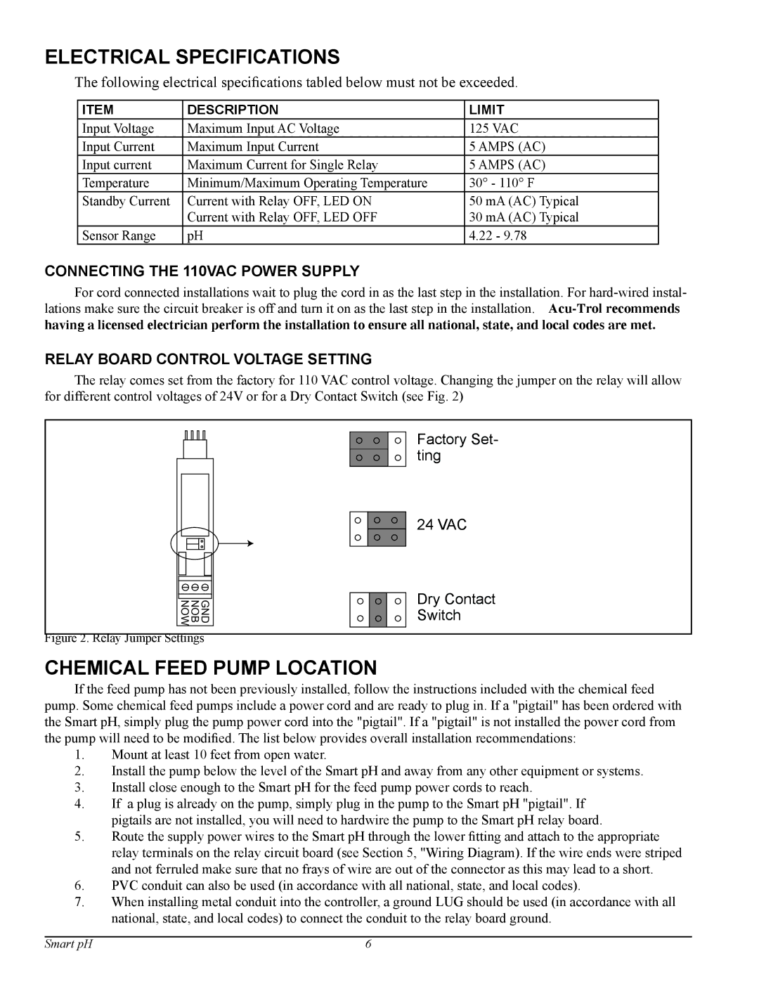
RELAY BOARD CONTROL VOLTAGE SETTING
The relay comes set from the factory for 110 VAC control voltage. Changing the jumper on the relay will allow for different control voltages of 24V or for a Dry Contact Switch (see Fig. 2)
GND
NOB
NOW
Figure 2. Relay Jumper Settings
CHEMICAL FEED PUMP LOCATION
Factory Set- ting
24 VAC
Dry Contact Switch
If the feed pump has not been previously installed, follow the instructions included with the chemical feed pump. Some chemical feed pumps include a power cord and are ready to plug in. If a "pigtail" has been ordered with the Smart pH, simply plug the pump power cord into the "pigtail". If a "pigtail" is not installed the power cord from the pump will need to be modified. The list below provides overall installation recommendations:
1.Mount at least 10 feet from open water.
2.Install the pump below the level of the Smart pH and away from any other equipment or systems.
3.Install close enough to the Smart pH for the feed pump power cords to reach.
4.If a plug is already on the pump, simply plug in the pump to the Smart pH "pigtail". If pigtails are not installed, you will need to hardwire the pump to the Smart pH relay board.
5.Route the supply power wires to the Smart pH through the lower fitting and attach to the appropriate relay terminals on the relay circuit board (see Section 5, "Wiring Diagram). If the wire ends were striped and not ferruled make sure that no frays of wire are out of the connector as this may lead to a short.
6.PVC conduit can also be used (in accordance with all national, state, and local codes).
7.When installing metal conduit into the controller, a ground LUG should be used (in accordance with all national, state, and local codes) to connect the conduit to the relay board ground.
Smart pH | 6 |