PLUMBING INSTALLATION
Install the flow sensor and the pH sensor using the following steps:
1.Turn off all power to the system, close all isolation valves and then release any air from the system by turning the release valve on top of the system filter.
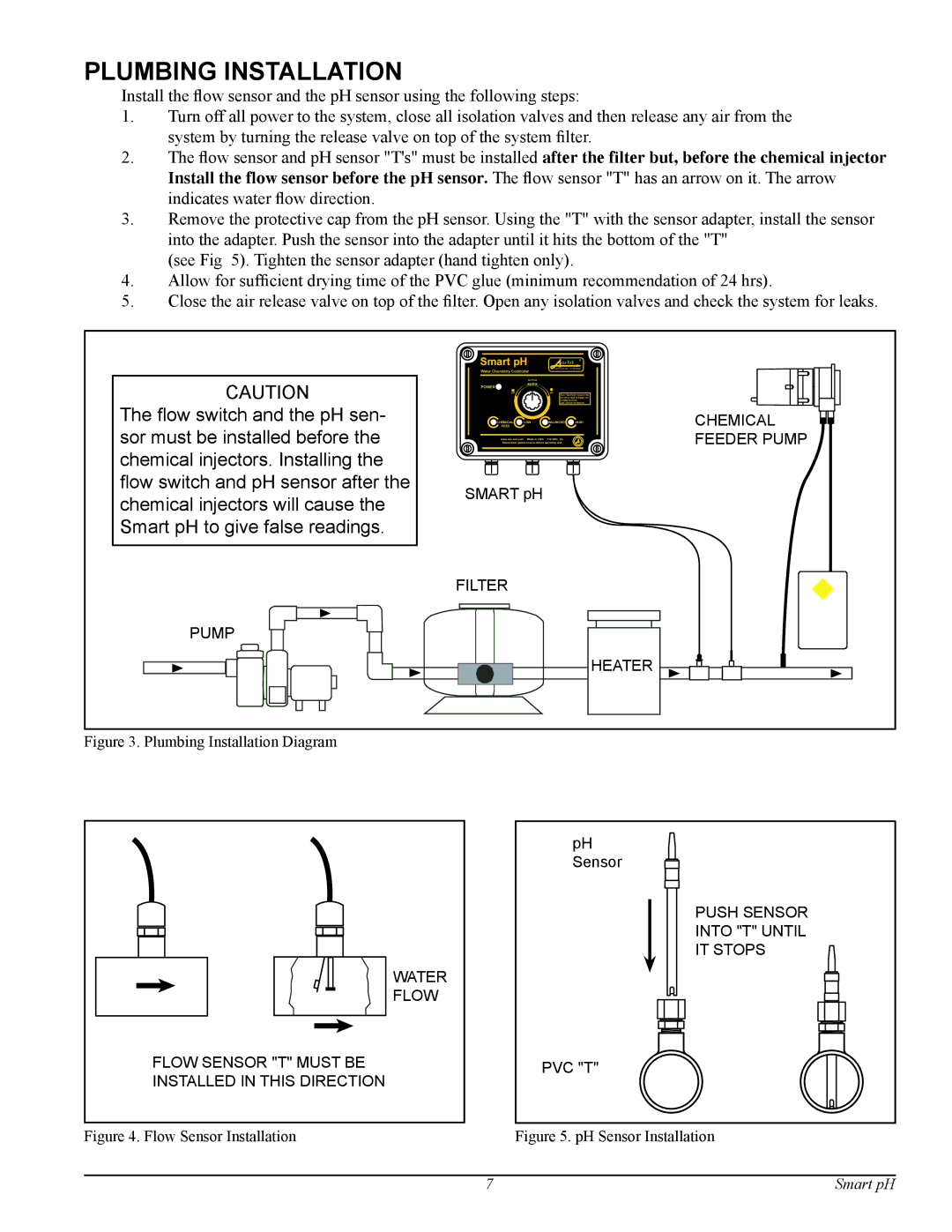
2.The flow sensor and pH sensor "T's" must be installed after the filter but, before the chemical injector Install the flow sensor before the pH sensor. The flow sensor "T" has an arrow on it. The arrow indicates water flow direction.
3.Remove the protective cap from the pH sensor. Using the "T" with the sensor adapter, install the sensor into the adapter. Push the sensor into the adapter until it hits the bottom of the "T"
(see Fig 5). Tighten the sensor adapter (hand tighten only).
4.Allow for sufficient drying time of the PVC glue (minimum recommendation of 24 hrs).
5.Close the air release valve on top of the filter. Open any isolation valves and check the system for leaks.
Smart pH
Water Chemistry Controller
PROGRAMMABLE CONTROLLERS
CAUTION
The flow switch and the pH sen- sor must be installed before the chemical injectors. Installing the flow switch and pH sensor after the chemical injectors will cause the Smart pH to give false readings.
PUMP
| Set Point |
POWER | pH |
| |
pH | pH |
Turn “Set Point” knob to the far left or right to trigger pH reading function
(see manual for details)
CHEMICAL | LOW | BALANCED | HIGH |
FEED |
|
|
|
Made in USA | 110 VAC, 5A |
|
Disconnect power source before servicing unit
SMART pH
FILTER
HEATER
CHEMICAL FEEDER PUMP
Figure 3. Plumbing Installation Diagram
WATER
FLOW
FLOW SENSOR "T" MUST BE
INSTALLED IN THIS DIRECTION
pH Sensor
PUSH SENSOR
INTO "T" UNTIL
IT STOPS
PVC "T"
Figure 4. Flow Sensor Installation | Figure 5. pH Sensor Installation |
7 | Smart pH |