SENSOR WIRING
pH SENSOR
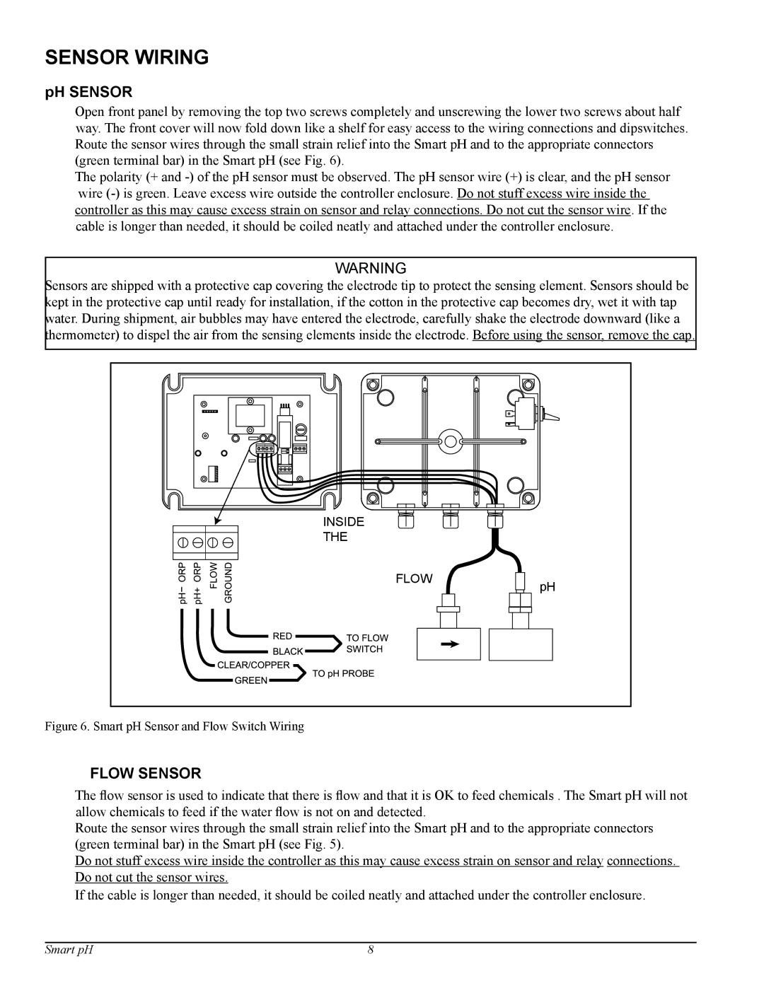
Open front panel by removing the top two screws completely and unscrewing the lower two screws about half way. The front cover will now fold down like a shelf for easy access to the wiring connections and dipswitches. Route the sensor wires through the small strain relief into the Smart pH and to the appropriate connectors (green terminal bar) in the Smart pH (see Fig. 6).
The polarity (+ and
WARNING
Sensors are shipped with a protective cap covering the electrode tip to protect the sensing element. Sensors should be kept in the protective cap until ready for installation, if the cotton in the protective cap becomes dry, wet it with tap water. During shipment, air bubbles may have entered the electrode, carefully shake the electrode downward (like a thermometer) to dispel the air from the sensing elements inside the electrode. Before using the sensor, remove the cap.
INSIDE
THE
FLOW
pH
Figure 6. Smart pH Sensor and Flow Switch Wiring
FLOW SENSOR
The flow sensor is used to indicate that there is flow and that it is OK to feed chemicals . The Smart pH will not allow chemicals to feed if the water flow is not on and detected.
Route the sensor wires through the small strain relief into the Smart pH and to the appropriate connectors (green terminal bar) in the Smart pH (see Fig. 5).
Do not stuff excess wire inside the controller as this may cause excess strain on sensor and relay connections. Do not cut the sensor wires.
If the cable is longer than needed, it should be coiled neatly and attached under the controller enclosure.
Smart pH | 8 |