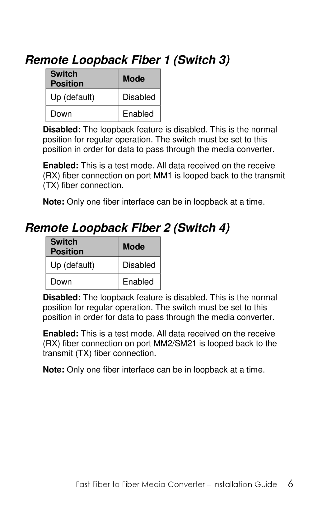
Remote Loopback Fiber 1 (Switch 3)
Switch |
| Mode |
|
Position |
|
| |
|
|
| |
Up (default) |
| Disabled | |
|
|
| |
Down |
| Enabled | |
|
|
|
|
Disabled: The loopback feature is disabled. This is the normal position for regular operation. The switch must be set to this position in order for data to pass through the media converter.
Enabled: This is a test mode. All data received on the receive (RX) fiber connection on port MM1 is looped back to the transmit (TX) fiber connection.
Note: Only one fiber interface can be in loopback at a time.
Remote Loopback Fiber 2 (Switch 4)
| Switch |
|
| Mode |
|
| Position |
|
|
| |
|
|
|
|
| |
| Up (default) |
| Disabled | ||
|
|
|
| ||
| Down |
| Enabled | ||
|
|
|
|
|
|
Disabled: The loopback feature is disabled. This is the normal position for regular operation. The switch must be set to this position in order for data to pass through the media converter.
Enabled: This is a test mode. All data received on the receive (RX) fiber connection on port MM2/SM21 is looped back to the transmit (TX) fiber connection.
Note: Only one fiber interface can be in loopback at a time.
Fast Fiber to Fiber Media Converter – Installation Guide 6