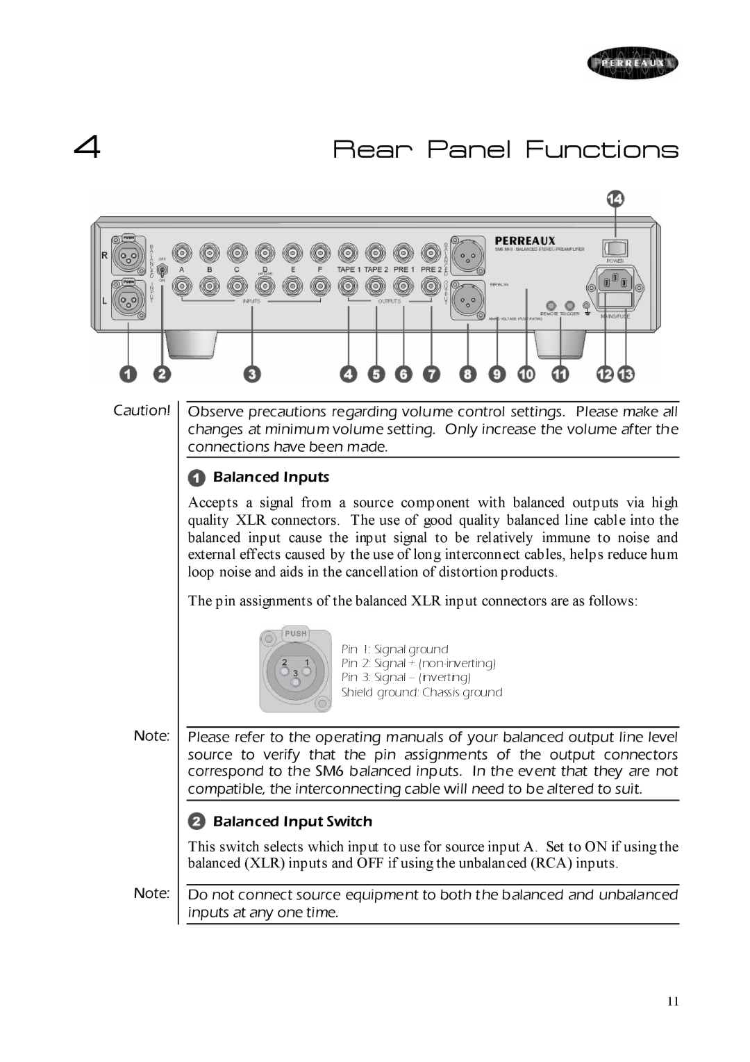
SM6 MKII specifications
The Perreaux SM6 MKII is an impressive amplifier that encapsulates the essence of high-fidelity audio performance, making it a remarkable choice for discerning audiophiles. Renowned for its robust build quality and sophisticated design, the SM6 MKII promises to deliver an immersive listening experience while showcasing the brand’s commitment to craftsmanship and innovation.At the heart of the SM6 MKII is a high-power solid-state amplifier circuit that ensures dynamic and accurate sound reproduction. With a power output of 100 watts per channel into 8 ohms, the amplifier can easily drive a wide range of loudspeakers. It is designed to handle the most demanding musical passages without distortion, making it suitable for both loud and nuanced listening environments.
One of the standout features of the SM6 MKII is its dual-mono design, which helps to eliminate crosstalk between the left and right channels. This design philosophy not only enhances stereo imaging but also provides a more immersive soundstage. The amp utilizes a high-performance toroidal transformer, known for its efficiency and minimal electromagnetic interference, further enhancing the clarity of the audio signal.
The SM6 MKII integrates advanced technologies, such as the unique feedback topology that helps minimize distortion and improve signal integrity. This technology ensures that the amplifier remains stable under varying load conditions, providing consistent performance regardless of speaker impedance or volume levels. Additionally, the high-current output stage significantly contributes to its dynamic capabilities, allowing for impressive transient response.
Another characteristic of the SM6 MKII is its user-friendly interface. The amplifier features intuitive knobs and switches that enable easy adjustment of volume, balance, and input selection. The robust chassis construction not only contributes to its aesthetic appeal but also serves to reduce vibration and external interference, ensuring that the audio integrity is preserved.
Overall, the Perreaux SM6 MKII stands out as an excellent investment for those who prioritize audio fidelity and performance. With its powerful output, sophisticated design, and innovative technologies, it is well-equipped to deliver a captivating listening experience that meets the demands of even the most discerning listeners. Whether you're enjoying music in a casual setting or critically listening for nuances, the SM6 MKII provides a sound experience that is both engaging and lifelike.

