A470 Users Guide
RS232 Serial Interface
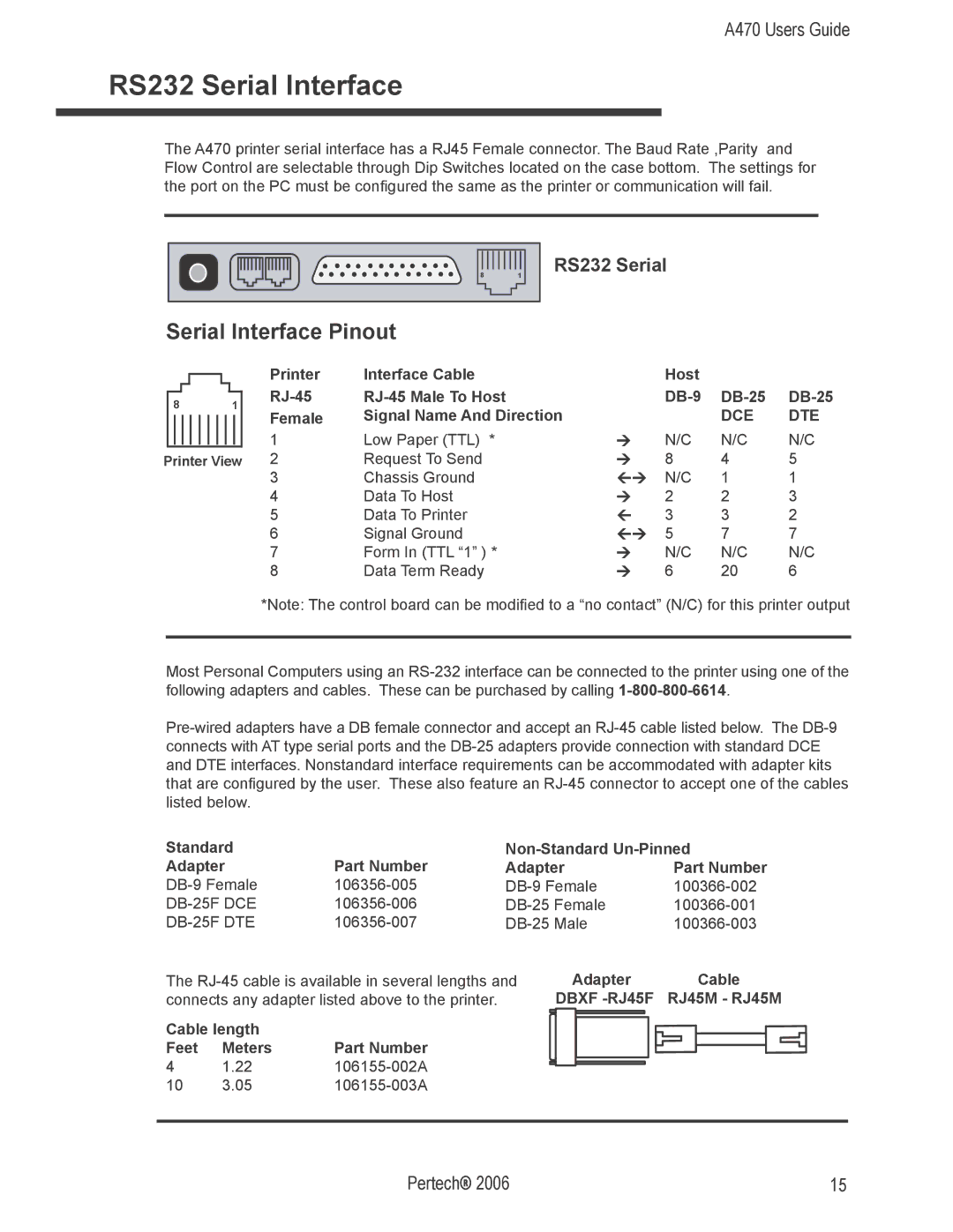
The A470 printer serial interface has a RJ45 Female connector. The Baud Rate ,Parity and Flow Control are selectable through Dip Switches located on the case bottom. The settings for the port on the PC must be configured the same as the printer or communication will fail.
81
RS232 Serial
Serial Interface Pinout
|
| Printer | Interface Cable |
| Host |
|
|
8 | 1 |
| |||||
Female | Signal Name And Direction |
|
| DCE | DTE | ||
|
|
|
| ||||
|
| 1 | Low Paper (TTL) * | Ú | N/C | N/C | N/C |
Printer View 2 | Request To Send | Ú | 8 | 4 | 5 | ||
|
| 3 | Chassis Ground | ÙÚ | N/C | 1 | 1 |
|
| 4 | Data To Host | Ú | 2 | 2 | 3 |
|
| 5 | Data To Printer | Ù | 3 | 3 | 2 |
|
| 6 | Signal Ground | ÙÚ | 5 | 7 | 7 |
|
| 7 | Form In (TTL “1” ) * | Ú | N/C | N/C | N/C |
|
| 8 | Data Term Ready | Ú | 6 | 20 | 6 |
*Note: The control board can be modified to a “no contact” (N/C) for this printer output
Most Personal Computers using an
Standard |
|
| |
Adapter | Part Number | Adapter | Part Number |
| |||
The
Cable length |
| |
Feet | Meters | Part Number |
4 | 1.22 | |
10 | 3.05 | |
Adapter Cable DBXF
Pertech® 2006 | 15 |