Quick Use | CONNECTING THE LX3500D DVD HOME CINEMA SYSTEM TO YOUR PROJECTION |
TV (MODELS 46PP9302, 55PP9352, 60PP9352, 55PP9502, AND 60PP9502) | |
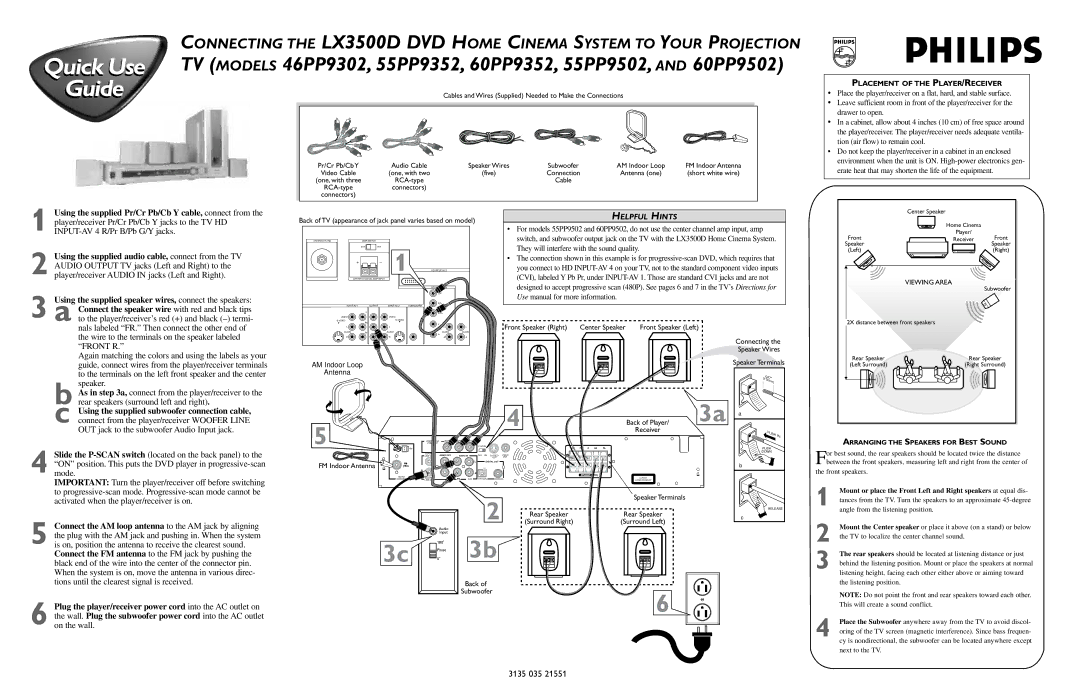
Guide | Cables and Wires (Supplied) Needed to Make the Connections |
|
|
|
|
|
|
|
|
| Pr/Cr Pb/Cb Y | Audio Cable | Speaker Wires | Subwoofer | AM Indoor Loop | FM Indoor Antenna |
|
| Video Cable | (one, with two | (five) | Connection | Antenna (one) | (short white wire) |
|
| (one, with three |
| Cable |
|
|
| |
| connectors) |
|
|
|
|
| |
| connectors) |
|
|
|
|
|
|
PLACEMENT OF THE PLAYER/RECEIVER
•Place the player/receiver on a flat, hard, and stable surface.
•Leave sufficient room in front of the player/receiver for the drawer to open.
•In a cabinet, allow about 4 inches (10 cm) of free space around the player/receiver. The player/receiver needs adequate ventila- tion (air flow) to remain cool.
•Do not keep the player/receiver in a cabinet in an enclosed environment when the unit is ON.
1
2
3
Using the supplied Pr/Cr Pb/Cb Y cable, connect from the player/receiver Pr/Cr Pb/Cb Y jacks to the TV HD
Using the supplied audio cable, connect from the TV AUDIO OUTPUT TV jacks (Left and Right) to the player/receiver AUDIO IN jacks (Left and Right).
Using the supplied speaker wires, connect the speakers: a Connect the speaker wire with red and black tips
Back of TV (appearance of jack panel varies based on model)
ANTENNA IN 75Ω | AMP SWITCH |
EXTINT
+ | _ | 1 |
|
|
|
| HD | ||
CENTER CHANNEL AMP INPUT |
|
|
| |
|
|
| HD | 4 |
|
|
|
| G/Y |
OUTPUT | SUBWOOFER | R/Pr | ||
| ||||
| Y |
|
| B/Pb |
HELPFUL HINTS
•For models 55PP9502 and 60PP9502, do not use the center channel amp input, amp switch, and subwoofer output jack on the TV with the LX3500D Home Cinema System. They will interfere with the sound quality.
•The connection shown in this example is for
| Center Speaker |
|
| Home Cinema |
|
Front | Player/ | Front |
Receiver | ||
Speaker |
| Speaker |
(Left) |
| (Right) |
VIEWING AREA
Subwoofer
to the player/receiver’s red (+) and black
Again matching the colors and using the labels as your guide, connect wires from the player/receiver terminals to the terminals on the left front speaker and the center speaker.
VIDEO |
| VIDEO |
|
|
|
|
|
|
|
|
|
|
| ||
L | Pb | L |
|
|
|
|
|
V |
|
| Front Speaker (Right) | Center Speaker | Front Speaker (Left) | ||
|
|
|
| ||||
L |
| SYNC | L | L | |||
| L |
|
|
| |||
AUDIO | Pr | AUDIO | AUDIO | AUDIO |
|
|
|
|
| H |
|
|
|
|
|
R |
| R | R | R |
|
|
|
AM Indoor Loop
Antenna
Connecting the Speaker Wires
Speaker Terminals
.047" | |
(12 | m |
| m) |
2X distance between front speakers
Rear Speaker | Rear Speaker |
(Left Surround) | (Right Surround) |
4
b As in step 3a, connect from the player/receiver to the rear speakers (surround left and right).
c Using the supplied subwoofer connection cable, connect from the player/receiver WOOFER LINE OUT jack to the subwoofer Audio Input jack.
Slide the
IMPORTANT: Turn the player/receiver off before switching to
5
FM Indoor Antenna
4 | Back of Player/ 3a |
Receiver |
| COMPONENT | PrCr | PbCb | Y |
|
|
|
|
|
|
| VIDEO OUT |
|
|
|
|
|
|
|
|
|
| AM |
|
|
|
|
| FR | SR | ||
|
|
|
|
|
|
|
| |||
| CENTER | AUDIO OU | AUDIO IN | OFF | ON | VIDEO | + | + | ||
| LINE OUT | |||||||||
|
|
|
|
|
|
| OUT | OUT |
|
|
|
|
|
|
|
| DIGITAL OUT |
|
|
| |
|
|
|
|
|
|
|
|
| - | - |
|
|
|
|
| R |
|
|
| SPEAKER | 4 |
AM/FM |
|
|
|
|
|
|
|
| ||
WOOFER |
|
| AUX | OPTICAL | COAXIAL |
| CLASS 1 | |||
ANTENNA | LINE OUT |
|
|
| LASER PRODUCT | |||||
a |
|
PU | SH |
| |
| IN |
PUSH |
|
DOWN |
|
b |
|
ARRANGING THE SPEAKERS FOR BEST SOUND
For best sound, the rear speakers should be located twice the distance between the front speakers, measuring left and right from the center of
the front speakers.
1 Mount or place the Front Left and Right speakers at equal dis-
5
6
activated when the player/receiver is on.
Connect the AM loop antenna to the AM jack by aligning the plug with the AM jack and pushing in. When the system is on, position the antenna to receive the clearest sound.
Connect the FM antenna to the FM jack by pushing the black end of the wire into the center of the connector pin. When the system is on, move the antenna in various direc- tions until the clearest signal is received.
Plug the player/receiver power cord into the AC outlet on the wall. Plug the subwoofer power cord into the AC outlet on the wall.
3c
Audio |
Input |
180 |
Phase |
0 |
2
3b
Back of
Subwoofer
| Speaker Terminals |
Rear Speaker | Rear Speaker |
(Surround Right) | (Surround Left) |
6
RELEASE |
c |
tances from the TV. Turn the speakers to an approximate
2 Mount the Center speaker or place it above (on a stand) or below the TV to localize the center channel sound.
3 The rear speakers should be located at listening distance or just behind the listening position. Mount or place the speakers at normal listening height, facing each other either above or aiming toward the listening position.
NOTE: Do not point the front and rear speakers toward each other. This will create a sound conflict.
4 Place the Subwoofer anywhere away from the TV to avoid discol- oring of the TV screen (magnetic interference). Since bass frequen- cy is nondirectional, the subwoofer can be located anywhere except next to the TV.
3135 035 21551