SP

IMPORTANTE

LEER ANTES

DE LA

INSTALACIÓN

12

La instalación de su antena puede estar sujeta a restricciones de altura u otras restricciones, dependiendo de su proximidad con un aeropuerto o de las normas locales.

Tómese el tiempo necesario para planificar el procedimiento de insta- lación. Realice todo el trabajo de montaje de la antena en la tierra. Levante la antena completa después del montaje.

NO realice el trabajo un día lluvioso, ventoso o que esté nevando, o si se está aproximando una tormenta eléctrica. NO utilice una escalera de metal.

Si el montaje de la antena comienza a caerse, aléjese y déjelo caer. Recuerde que el soporte vertical de la antena y el cable son exce- lentes conductores de la corriente eléctrica.

NO instale la antena usted solo.Asegúrese de contar con otras dos personas que colaboren con usted.

Si cualquier parte de la antena entra en contacto con una línea de corriente . . . NO LA TOQUE NI INTENTE QUITARLA USTED MISMO. Comuníquese de inmediato con la compañía de electricidad local. Ellos se encargarán de quitarla.

Si ocurre un accidente eléctrico . . . NO TOQUE A LA PERSONA EN CONTACTO CON EL CABLE DE CORRIENTE, o usted también puede resultar electrocutado. Use una tabla, palo o cuerda SECOS para empujar o tirar de la víctima para alejarla de los cables de corri- ente y la antena. Una vez que la persona esté alejada, examínela. Si ha dejado de respirar, adminístrele de inmediato el procedimiento de resucitación cardiopulmonar (CPR, por su sigla en inglés) y permanez- ca con ella. Haga que alguien llame a la asistencia médica.

Instale los cables de la antena a una altura suficiente como para que las personas no entren en contacto con ellos al caminar.

No instale el o los cables de la antena sobre o por debajo de las líneas de los servicios públicos.

Nota: Para la insta- lación final y la conexión de la ante- na pueden necesi- tarse herramientas adicionales.Antes de iniciar el montaje, lea atentamente las instrucciones para determinar sus requerimientos específicos.

SP

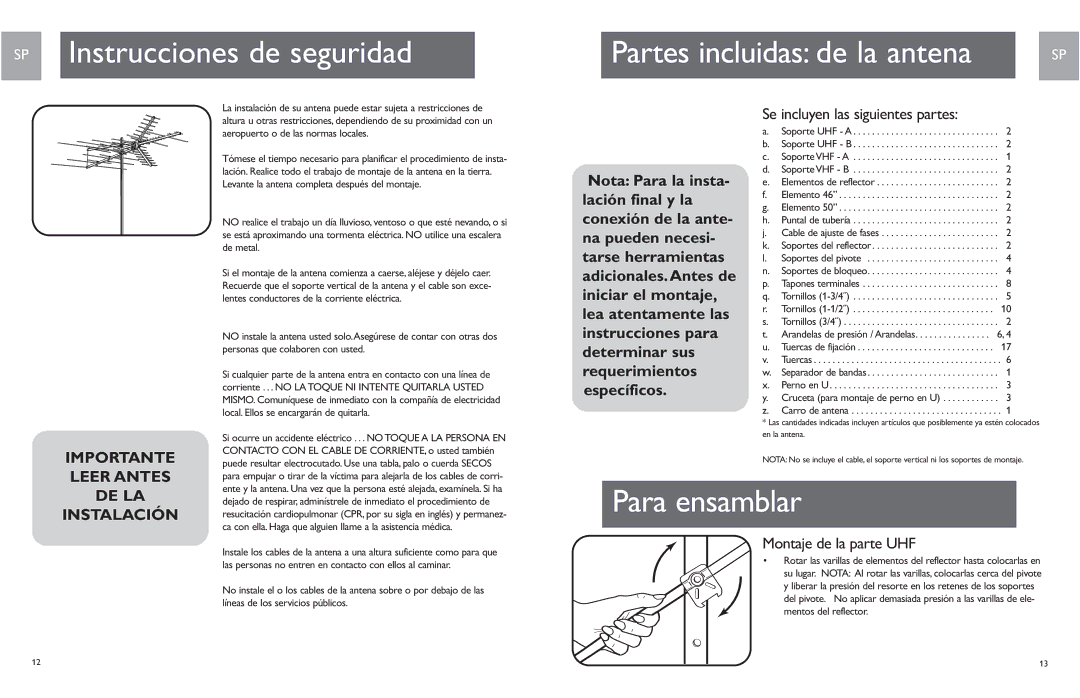
Se incluyen las siguientes partes:

a. Soporte UHF - A . . . . . . . . . . . . . . . . . . . . . . . . . . . . . . . 2 b. Soporte UHF - B . . . . . . . . . . . . . . . . . . . . . . . . . . . . . . . 2 c. Soporte VHF - A . . . . . . . . . . . . . . . . . . . . . . . . . . . . . . . 1 d. Soporte VHF - B . . . . . . . . . . . . . . . . . . . . . . . . . . . . . . . 2 e. Elementos de reflector . . . . . . . . . . . . . . . . . . . . . . . . . . 2 f. Elemento 46” . . . . . . . . . . . . . . . . . . . . . . . . . . . . . . . . . . 2 g. Elemento 50” . . . . . . . . . . . . . . . . . . . . . . . . . . . . . . . . . . 2 h. Puntal de tubería . . . . . . . . . . . . . . . . . . . . . . . . . . . . . . . 2 j. Cable de ajuste de fases . . . . . . . . . . . . . . . . . . . . . . . . . 2 k. Soportes del reflector . . . . . . . . . . . . . . . . . . . . . . . . . . . 2 l. Soportes del pivote . . . . . . . . . . . . . . . . . . . . . . . . . . . . 4 n. Soportes de bloqueo. . . . . . . . . . . . . . . . . . . . . . . . . . . . 4 p. Tapones terminales . . . . . . . . . . . . . . . . . . . . . . . . . . . . . 8 q. Tornillos (1-3/4˝) . . . . . . . . . . . . . . . . . . . . . . . . . . . . . . . 5 r. Tornillos (1-1/2˝) . . . . . . . . . . . . . . . . . . . . . . . . . . . . . . 10 s. Tornillos (3/4˝) . . . . . . . . . . . . . . . . . . . . . . . . . . . . . . . . . 2 t. Arandelas de presión / Arandelas. . . . . . . . . . . . . . . . 6, 4 u. Tuercas de fijación . . . . . . . . . . . . . . . . . . . . . . . . . . . . . 17 v. Tuercas . . . . . . . . . . . . . . . . . . . . . . . . . . . . . . . . . . . . . . . . 6 w. Separador de bandas . . . . . . . . . . . . . . . . . . . . . . . . . . . . 1 x. Perno en U. . . . . . . . . . . . . . . . . . . . . . . . . . . . . . . . . . . . 3 y. Cruceta (para montaje de perno en U) . . . . . . . . . . . . 3 z. Carro de antena . . . . . . . . . . . . . . . . . . . . . . . . . . . . . . . . 1

* Las cantidades indicadas incluyen artículos que posiblemente ya estén colocados en la antena.

NOTA: No se incluye el cable, el soporte vertical ni los soportes de montaje.

Montaje de la parte UHF

• Rotar las varillas de elementos del reflector hasta colocarlas en su lugar. NOTA: Al rotar las varillas, colocarlas cerca del pivote y liberar la presión del resorte en los retenes de los soportes del pivote. No aplicar demasiada presión a las varillas de ele- mentos del reflector.

13

Page 7
Image 7
Philips SDV9011K/17, MANT901EN user manual Se incluyen las siguientes partes, Montaje de la parte UHF

SDV9011K/17, MANT901EN specifications

The Philips SDV9011K/17 and the MANT901EN are advanced television antennas designed to enhance your viewing experience by delivering high-quality digital signals. These models are characterized by their innovative design, superior performance, and user-friendly features, making them ideal for anyone looking to improve their TV reception without the hassle of satellite subscriptions or cable services.

The Philips SDV9011K/17 is an indoor antenna that boasts a sleek and modern aesthetics, allowing it to complement any interior without being obtrusive. This model supports a wide range of frequencies, making it highly versatile for different broadcasting standards. Equipped with a built-in amplifier, the SDV9011K/17 enhances signal strength, ensuring that you receive clear and stable channels, even in areas with weak reception. It supports HD and 4K content, making it a perfect choice for tech enthusiasts who demand the best visual quality for their favorite shows and sports events.

Another notable feature of the SDV9011K/17 is its easy installation process. The antenna can be set up in minutes, with no need for specialized tools or complex configurations. Users can position it on a tabletop, mount it on the wall, or stick it to a window for optimal signal strength, ensuring flexible placement options based on individual room layouts.

Meanwhile, the Philips MANT901EN is an outdoor antenna that takes performance to the next level. Its robust design is built to withstand harsh weather conditions, making it a reliable option for those living in challenging environments. With a longer range and advanced signal-gathering capabilities, the MANT901EN is capable of picking up signals from greater distances compared to standard indoor antennas.

The MANT901EN features a multi-directional design, eliminating the need for constant adjustments. Its innovative technology ensures that users can enjoy a wide variety of channels without the frustration of signal dropouts. Additionally, the antenna’s compact design makes it easy to install without taking up much space or diminishing the aesthetics of your property's exterior.

In conclusion, both the Philips SDV9011K/17 and MANT901EN antennas represent a smart choice for those seeking to enhance their television viewing experience. Their blend of modern design, easy installation, and superior performance characteristics ensure viewers can enjoy high-quality digital content without the added cost of cable subscriptions. Whether you are limited to indoor spaces or have the flexibility of an outdoor setup, Philips has solutions tailored for maximized enjoyment of free-to-air broadcasting.