Philips SemiconductorsUser’s Manual - Preliminary -


GENERAL DESCRIPTION


P89LPC901/902/903


Name

Description

SFR


Bit Functions and Addresses


Reset Value


Address

MSB


LSB

Hex

Binary


TH0

Timer 0 High

8CH


00H

00000000


TH1

Timer 1 High

8DH


00H

00000000


TL0

Timer 0 Low

8AH


00H

00000000


TL1

Timer 1 Low

8BH


00H

00000000


TMOD

Timer 0 and 1 Mode

89H

-


-

T1M1

T1M0

-

-

T0M1

T0M0

00H

00000000


TRIM#

Internal Oscillator Trim Register

96H

-


-

TRIM.5

TRIM.4

TRIM.3

TRIM.2

TRIM.1

TRIM.0

Notes 4,5


WDCON#

Watchdog Control Register

A7H

PRE2


PRE1

PRE0

-

-

WDRUN

WDTOF

WDCLK

Notes 3,5


WDL#

Watchdog Load

C1H


FFH

11111111


WFEED1#

Watchdog Feed 1

C2H


WFEED2#

Watchdog Feed 2

C3H


Notes:

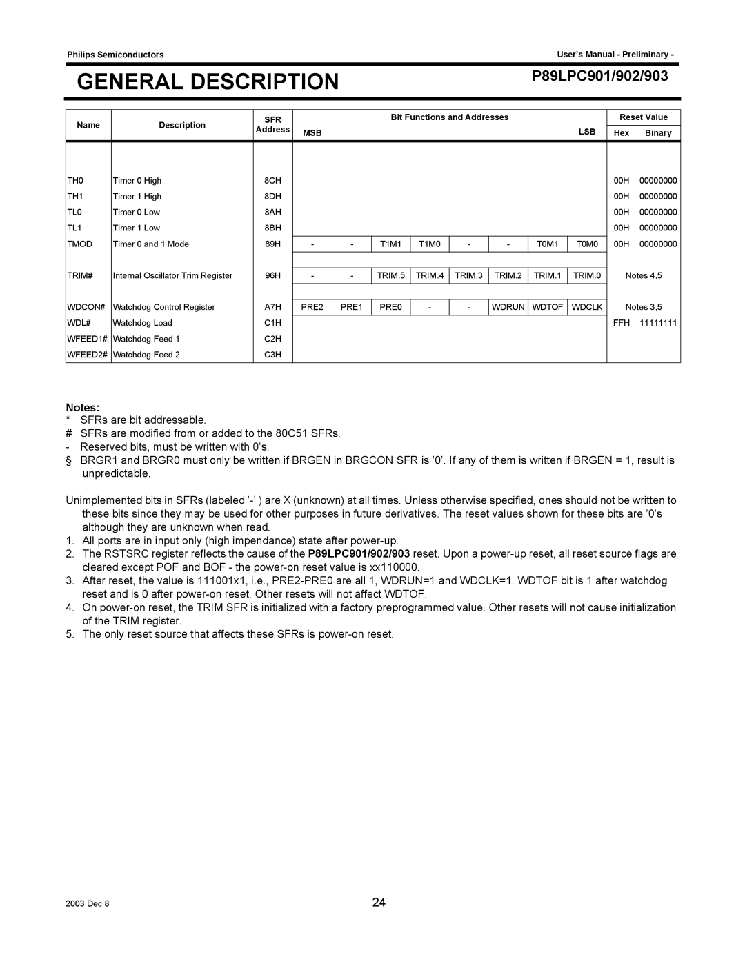
* SFRs are bit addressable.

#SFRs are modified from or added to the 80C51 SFRs. - Reserved bits, must be written with 0’s.

§ BRGR1 and BRGR0 must only be written if BRGEN in BRGCON SFR is ’0’. If any of them is written if BRGEN = 1, result is unpredictable.

Unimplemented bits in SFRs (labeled ’-’ ) are X (unknown) at all times. Unless otherwise specified, ones should not be written to these bits since they may be used for other purposes in future derivatives. The reset values shown for these bits are ’0’s although they are unknown when read.

1.All ports are in input only (high impendance) state after power-up.

2.The RSTSRC register reflects the cause of the P89LPC901/902/903 reset. Upon a power-up reset, all reset source flags are cleared except POF and BOF - the power-on reset value is xx110000.

3.After reset, the value is 111001x1, i.e., PRE2-PRE0 are all 1, WDRUN=1 and WDCLK=1. WDTOF bit is 1 after watchdog reset and is 0 after power-on reset. Other resets will not affect WDTOF.

4.On power-on reset, the TRIM SFR is initialized with a factory preprogrammed value. Other resets will not cause initialization of the TRIM register.

5.The only reset source that affects these SFRs is power-on reset.

2003 Dec 8

24

Page 24
Image 24
Philips P89LPC901, P89LPC903, P89LPC902 user manual TRIM.5 TRIM.4 TRIM.3 TRIM.2 TRIM.1 TRIM.0 WDCON#

P89LPC903, P89LPC902, P89LPC901 specifications

The Philips P89LPC901, P89LPC902, and P89LPC903 are a series of 8-bit microcontrollers designed for embedded system applications. These models, which belong to the LPC900 series, are notable for their affordability and versatility, making them an attractive choice for both hobbyists and professional developers.

One of the core features of the P89LPC901, P89LPC902, and P89LPC903 microcontrollers is their powerful 8-bit architecture. Operating at clock speeds up to 20 MHz, they deliver efficient performance suited for a range of tasks. Each model includes a comprehensive instruction set that supports various data manipulation and arithmetic functions, enabling extensive programming capabilities.

These microcontrollers come with built-in memory, with configurations that vary among the three models. The P89LPC901 typically features 4 KB of Flash memory and 256 bytes of RAM, while the P89LPC902 and P89LPC903 offer enhanced memory options. This Flash memory allows for reprogrammability, making it easier to update and modify applications as needed.

Another significant characteristic of the LPC900 series is their integrated peripherals. These models are equipped with a variety of I/O ports, allowing for easy interfacing with other devices and components. The P89LPC901 supports up to 32 I/O pins, while the P89LPC902 and P89LPC903 provide additional features such as analog-to-digital converters (ADCs), timers, and serial communication interfaces. This broad range of peripherals empowers developers to design complex applications without needing extra hardware.

Power consumption is also a key consideration for microcontroller applications. The P89LPC901, P89LPC902, and P89LPC903 are designed with low power consumption in mind, making them ideal for battery-operated devices and energy-efficient projects. They can operate in various power modes, allowing for greater flexibility in deployment.

In terms of technology, these microcontrollers utilize advanced CMOS technology, ensuring high reliability and durability. Their design offers a robust solution for numerous applications, including consumer electronics, industrial controls, and automation systems.

In summary, the Philips P89LPC901, P89LPC902, and P89LPC903 microcontrollers present an attractive combination of performance, integrated peripherals, low power consumption, and versatility. Their features cater to a wide array of applications, keeping them relevant in a rapidly evolving technology landscape. For hobbyists and professionals alike, these microcontrollers represent a reliable foundation for embedded system development.