SmartPanel Projector Driver Application Note | Panasonic |
II. CONTROL WIRING
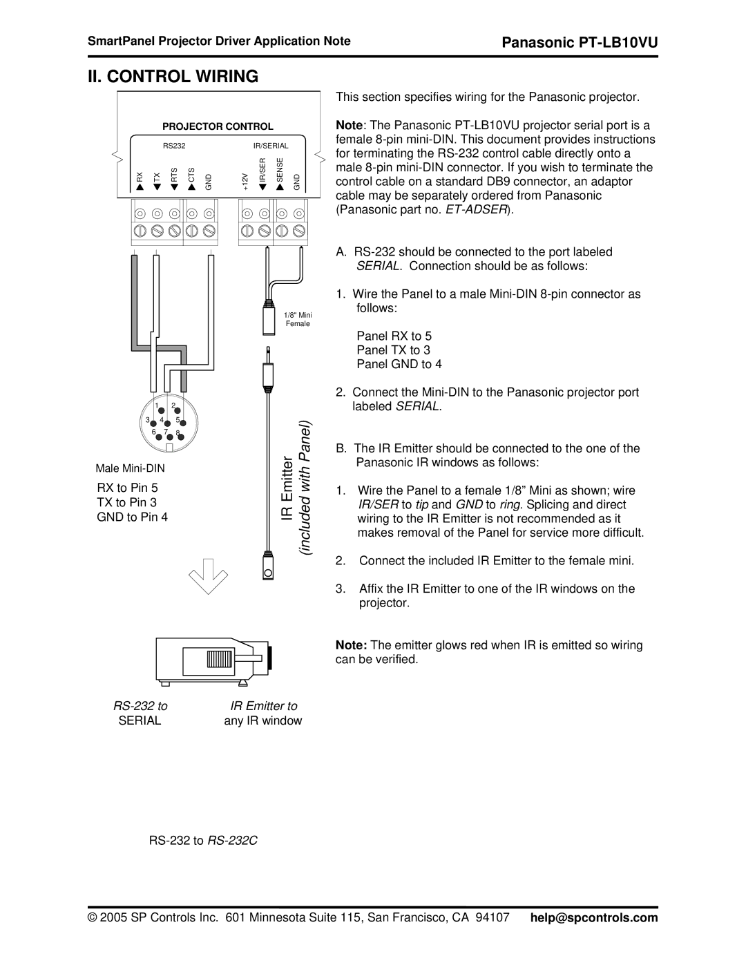
PROJECTOR CONTROL
|
| RS232 |
|
|
| IR/SERIAL |
| |
RX | TX | RTS | CTS | GND | +12V | IR/SER | SENSE | GND |
|
| 1/8" Mini | |
|
| Female | |
1 |
| 2 |
|
3 | 4 | 5 | with(includedPanel) |
6 | 7 | EmitterIR | |
8 |
| ||
Male |
|
| |
RX to Pin 5 |
|
|
|
TX to Pin 3 |
|
|
|
GND to Pin 4 |
|
| |
This section specifies wiring for the Panasonic projector.
Note: The Panasonic
A.
1.Wire the Panel to a male
Panel RX to 5
Panel TX to 3
Panel GND to 4
2.Connect the
B.The IR Emitter should be connected to the one of the Panasonic IR windows as follows:
1.Wire the Panel to a female 1/8” Mini as shown; wire IR/SER to tip and GND to ring. Splicing and direct wiring to the IR Emitter is not recommended as it makes removal of the Panel for service more difficult.
2.Connect the included IR Emitter to the female mini.
3.Affix the IR Emitter to one of the IR windows on the projector.
Note: The emitter glows red when IR is emitted so wiring can be verified.
IR Emitter to | |
SERIAL | any IR window |
© 2005 SP Controls Inc. 601 Minnesota Suite 115, San Francisco, CA 94107 help@spcontrols.com