MORE PIP |
|
| ||||||
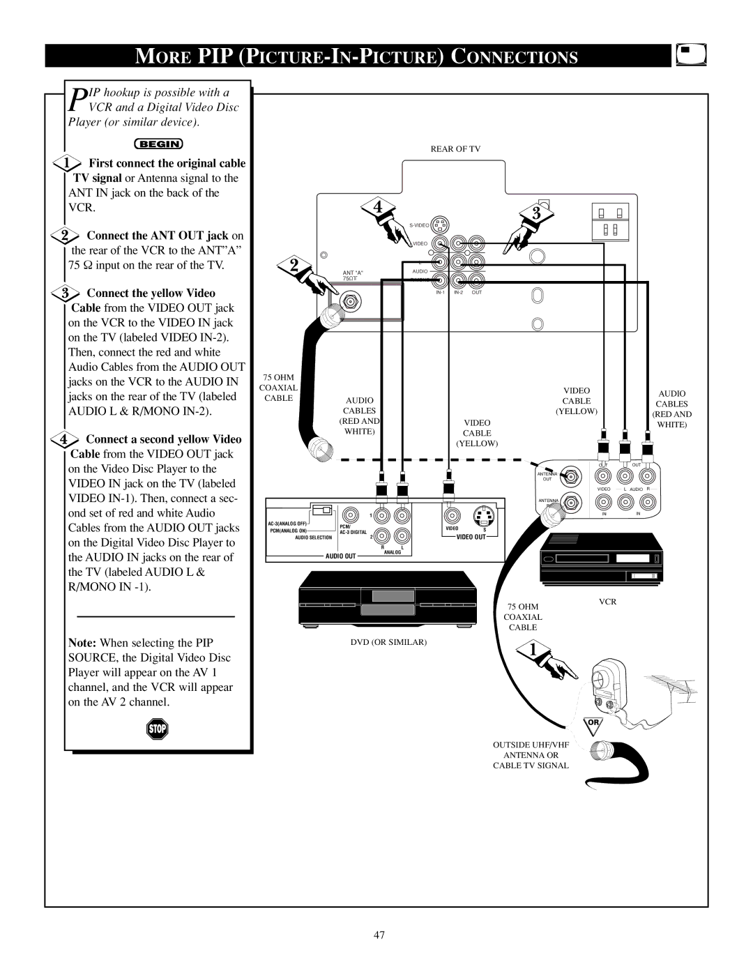
IP hookup is possible with a |
|
|
|
|
|
|
|
|
PVCR and a Digital Video Disc |
|
|
|
|
|
|
|
|
Player (or similar device). |
|
|
|
|
|
|
|
|
BEGIN |
|
|
| REAR OF TV |
|
| ||
|
|
|
|
|
| |||
First connect the original cable |
|
|
|
|
|
|
|
|
TV signal or Antenna signal to the |
|
|
|
|
|
|
|
|
ANT IN jack on the back of the |
| 4 |
|
|
|
|
|
|
VCR. |
|
|
|
| 3 |
|
| |
|
|
|
|
|
|
| ||
Connect the ANT OUT jack on |
|
|
|
|
|
|
| |
|
|
| VIDEO |
|
|
|
| |
the rear of the VCR to the ANT”A” |
|
|
|
|
|
|
| |
2 |
|
|
|
|
|
|
| |
75 Ω input on the rear of the TV. | ANT "A" |
| AUDIO |
|
|
|
| |
|
|
|
| L |
|
|
|
|
Connect the yellow Video |
| 75 |
| R/MONO |
|
|
|
|
|
|
| OUT |
|
| |||
Cable from the VIDEO OUT jack |
|
|
|
|
|
|
|
|
on the VCR to the VIDEO IN jack |
|
|
|
|
|
|
|
|
on the TV (labeled VIDEO |
|
|
|
|
|
|
|
|
Then, connect the red and white |
|
|
|
|
|
|
|
|
Audio Cables from the AUDIO OUT | 75 OHM |
|
|
|
|
|
|
|
jacks on the VCR to the AUDIO IN |
|
|
|
|
|
|
| |
COAXIAL |
|
|
|
| VIDEO |
|
| |
jacks on the rear of the TV (labeled |
|
|
|
|
| AUDIO | ||
CABLE |
|
|
|
|
| |||
AUDIO |
|
|
| CABLE |
| |||
AUDIO L & R/MONO |
|
|
|
|
| CABLES | ||
| CABLES |
|
|
| (YELLOW) |
| ||
|
|
|
|
| (RED AND | |||
|
| (RED AND |
|
|
| VIDEO |
| WHITE) |
Connect a second yellow Video |
| WHITE) |
|
|
| CABLE |
|
|
|
|
|
| (YELLOW) |
|
| ||
Cable from the VIDEO OUT jack |
|
|
|
|
|
| ||
|
|
|
|
|
|
|
| |
on the Video Disc Player to the |
|
|
|
|
|
| OUT | OUT |
|
|
|
|
| ANTENNA |
|
| |
VIDEO IN jack on the TV (labeled |
|
|
|
|
| OUT |
|
|
|
|
|
|
| VIDEO | L AUDIO R | ||
VIDEO |
|
|
|
|
| |||
|
|
|
|
| ANTENNA |
|
| |
ond set of red and white Audio |
|
|
|
|
| IN |
|
|
| 1 |
|
|
|
| IN | IN | |
Cables from the AUDIO OUT jacks |
|
| VIDEO | S |
|
| ||
PCM(ANALOG ON) |
|
|
|
| ||||
|
| PCM/ |
|
|
|
|
|
|
on the Digital Video Disc Player to | AUDIO SELECTION | 2 |
|
| VIDEO OUT |
|
| |
| R | ANALOG | L |
|
|
|
| |
the AUDIO IN jacks on the rear of | AUDIO OUT |
|
|
|
|
| ||
|
|
|
|
|
| |||
the TV (labeled AUDIO L & |
|
|
|
|
|
|
|
|
R/MONO IN |
|
|
|
|
|
|
|
|
|
|
|
|
|
| 75 OHM | VCR |
|
|
|
|
|
|
|
|
| |
|
|
|
|
|
| COAXIAL |
|
|
|
|
|
|
|
| CABLE |
|
|
Note: When selecting the PIP |
| DVD (OR SIMILAR) |
| 1 |
|
| ||
SOURCE, the Digital Video Disc |
|
|
|
|
|
|
| |
|
|
|
|
|
|
|
| |
Player will appear on the AV 1 |
|
|
|
|
|
|
|
|
channel, and the VCR will appear |
|
|
|
|
|
|
|
|
on the AV 2 channel. |
|
|
|
|
|
|
|
|
|
|
|
|
|
| OR |
|
|
|
|
|
|
|
| OUTSIDE UHF/VHF |
|
|
|
|
|
|
|
| ANTENNA OR |
|
|
|
|
|
|
|
| CABLE TV SIGNAL |
|
|
|
| 47 |
|
|
|
|
| |