CONNECTIONS
When connecting the units or changing their connections, be sure to turn off the power switch and disconnect the power cord from the outlet.
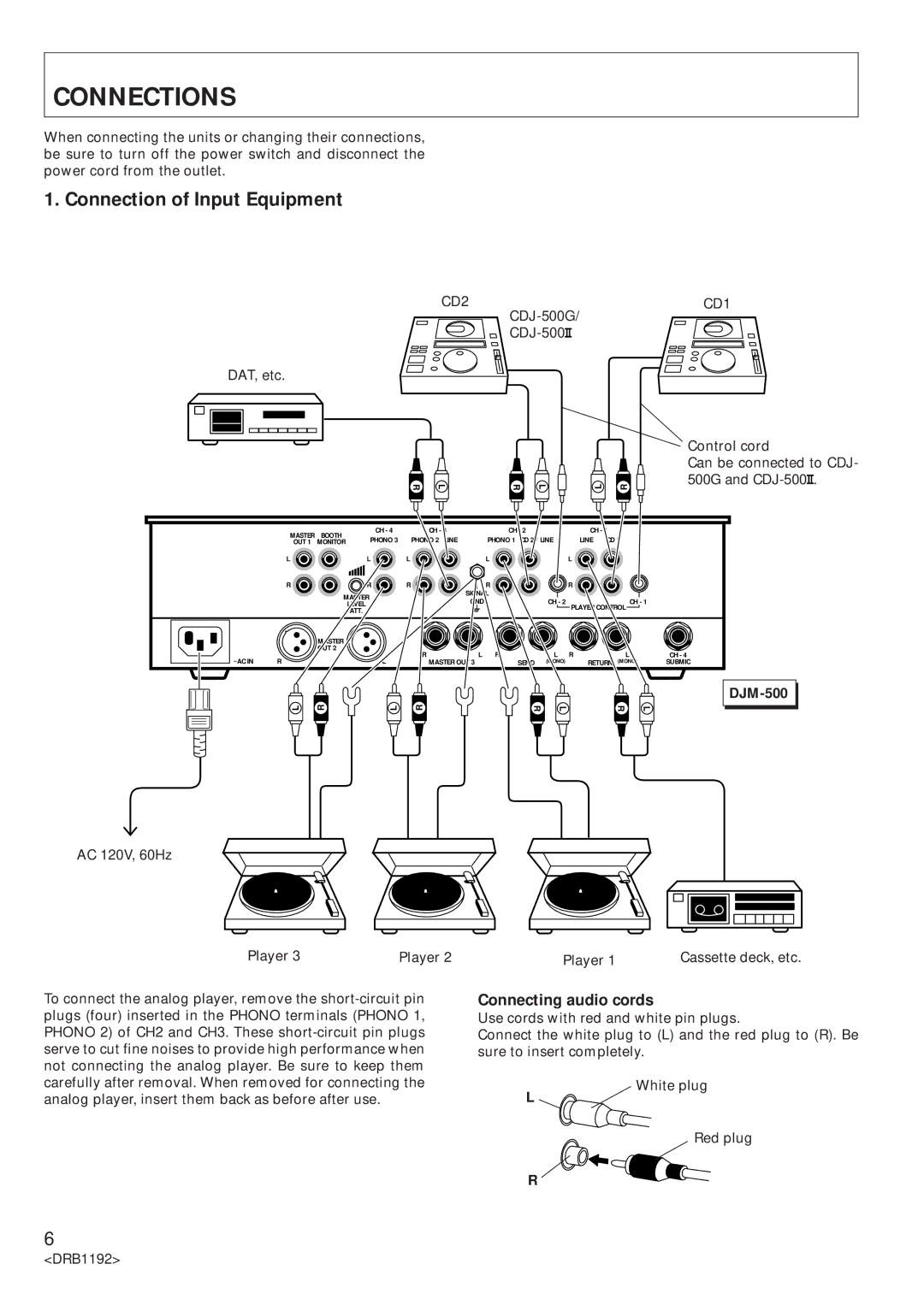
1. Connection of Input Equipment
CD2 | CD1 |
| |
|
DAT, etc.
R
L | R | L | L | R |
Control cord
Can be connected to CDJ- 500G and ![]() .
.
MASTER | BOOTH | CH - 4 | CH - 3 | CH - 2 | CH - 1 | |
PHONO 3 | PHONO 2 LINE | PHONO 1 CD 2 / LINE | LINE CD 1 | |||
OUT 1 | MONITOR | |||||
|
|
|
| |||
L |
| L | L | L | L |
| R | R | R | R |
| R |
|
|
|
| MASTER |
| SIGNAL |
|
|
|
|
|
|
| GND | CH - 2 |
| CH - 1 |
| |
|
| LEVEL |
|
|
| |||
|
|
|
|
| PLAYER CONTROL |
| ||
|
| ATT. |
|
|
|
| ||
|
|
|
|
|
|
|
| |
|
| MASTER |
|
|
|
|
|
|
|
| OUT 2 | R | L R | L | R | L | CH - 4 |
~AC IN |
|
| ||||||
R |
| L | MASTER OUT 3 | SEND (MONO) |
| RETURN (MONO) | SUBMIC | |
L | R | L | R | R | L | R | L |
DJM-500 

AC 120V, 60Hz
Player 3 | Player 2 |
To connect the analog player, remove the
Player 1 | Cassette deck, etc. |
Connecting audio cords
Use cords with red and white pin plugs.
Connect the white plug to (L) and the red plug to (R). Be sure to insert completely.
White plug
L
Red plug
R
6
<DRB1192>