Connections
Be sure to turn off the power and unplug the power cord from the power outlet whenever making or changing connections. Refer to the operating instructions for the component to be connected.
Connect the power cord after all the connections between devices have been completed.
Rear Panel
1 |
|
|
|
| 2 |
| 3 |
|
| 4 |
| 3 |
|
| 4 |
| 4 |
| 5 |
|
|
|
| 4 |
|
| 5 |
| 6 |
| 7 | ||||||||
|
|
|
|
|
|
|
|
|
|
|
|
|
|
|
|
|
|
|
|
|
|
|
|
|
|
|
|
|
|
|
|
|
|
|
|
|
|
|
|
|
|
|
|
|
|
|
|
|
|
|
|
|
|
|
|
|
|
|
|
|
|
|
|
|
|
|
|
|
|
|
|
|
|
|
|
|
|
|
|
|
|
|
|
|
|
|
|
|
|
|
|
|
|
|
|
|
|
|
|
|
|
|
|
|
|
|
|
|
|
|
|
|
|
|
|
|
|
|
|
English
R | L | ZONE | LINE L CD |
|
|
|
| 3 COLD 1 GND |
|
|
|
|
|
|
| CONTROL | CONTROL MIC 3 |
|
| 2 HOT |
|
|
|
|
|
|
|
|
|
| |
|
|
| ZONEATT. |
| R |
|
| R |
| R | R |
|
|
|
| MASTER1 | R | L | MASTER2 | R | L | REC OUT | R BOOTH L | R SEND L(MONO) | R | RETURN L(MONO) | |
|
| 1 GND |
|
| (TRS) |
|
|
| |||||
|
|
|
|
|
|
|
|
|
|
|
|
| |
R | L | 3 COLD 2 HOT MASTERATT. |
|
|
|
|
|
|
|
|
|
| |
| 17 |
| 16 |
| 15 |
| 14 |
| 13 |
| 12 |
| 11 |
| 10 |
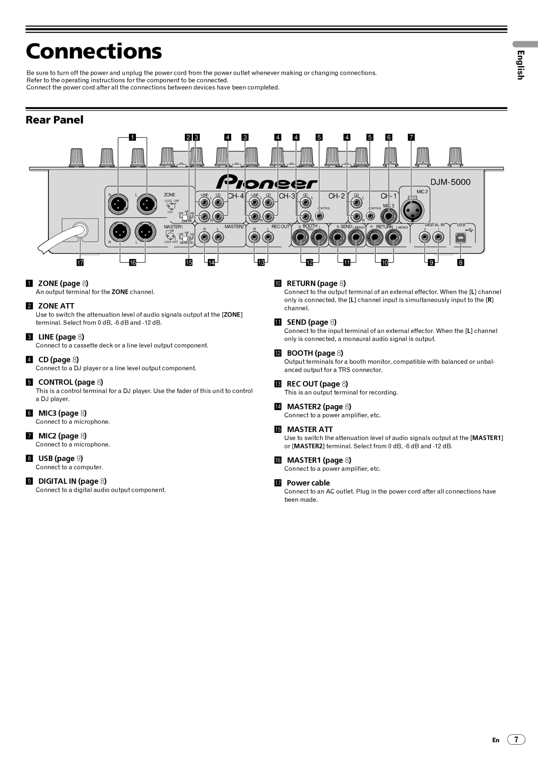
1 ZONE (page 8) |
|
|
|
|
|
|
| A RETURN (page 8) |
|
| |||||
DJM-5000
MIC 2
DIGITAL IN | USB |
2 1
9 8
An output terminal for the ZONE channel.
2ZONE ATT
Use to switch the attenuation level of audio signals output at the [ZONE] terminal. Select from 0 dB,
3LINE (page 8)
Connect to a cassette deck or a line level output component.
4CD (page 8)
Connect to a DJ player or a line level output component.
Connect to the output terminal of an external effector. When the [L] channel only is connected, the [L] channel input is simultaneously input to the [R] channel.
BSEND (page 8)
Connect to the input terminal of an external effector. When the [L] channel only is connected, a monaural audio signal is output.
CBOOTH (page 8)
Output terminals for a booth monitor, compatible with balanced or unbal- anced output for a TRS connector.
5CONTROL (page 8)
This is a control terminal for a DJ player. Use the fader of this unit to control a DJ player.
6MIC3 (page 8)
Connect to a microphone.
7MIC2 (page 8)
Connect to a microphone.
DREC OUT (page 8)
This is an output terminal for recording.
EMASTER2 (page 8)
Connect to a power amplifier, etc.
FMASTER ATT
Use to switch the attenuation level of audio signals output at the [MASTER1] or [MASTER2] terminal. Select from 0 dB,
8 | USB (page 9) | G MASTER1 (page 8) |
| Connect to a computer. | Connect to a power amplifier, etc. |
9 | DIGITAL IN (page 8) | H Power cable |
| Connect to a digital audio output component. | Connect to an AC outlet. Plug in the power cord after all connections have |
been made.
En 7