CONNECTIONS
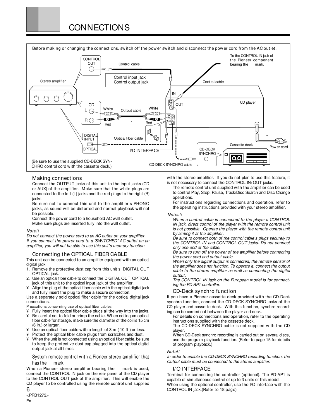
Before making or changing the connections, switch off the power switch and disconnect the power cord from the AC outlet.
CONTROL
OUT
Stereo amplifier
CControl cable
÷Control input jack
÷Control output jack
To the CONTROL IN jack of the Pioneer component
= bearing the Î mark.
C
Control cable
CD
L | White | Output cable | White |
|
IN |
|
OUT | CD player |
|
| L | L | |
R | R | Red | |
|
| R | |
| Red |
| |
DIGITAL |
| BOptical fiber cable |
|
INPUT |
|
| |
![]()
Cassette deck
OPTICAL | E I/O INTERFACE |
Power cord
DSYNCHRO
(Be sure to use the supplied
CHRO control cord with the cassette deck.) | |
|
AMaking connections
1Connect the OUTPUT jacks of this unit to the input jacks (CD or AUX) of the amplifier. Make sure that the white plugs are
connected to the left (L) jacks and the red plugs to the right (R) jacks.
÷Be sure not to connect this unit to the amplifier’s PHONO jacks, as sound will be distorted and normal playback will not be possible.
2Connect the power cord to a household AC wall outlet. ÷ Make sure plugs are inserted fully into the wall outlet.
Note!!
Do not connect the power cord to an AC outlet on your amplifier. If you connect the power cord to a "SWITCHED" AC outlet on an amplifier, you will not be able to use this unit's memory function.
BConnecting the OPTICAL FIBER CABLE
This unit can be connected to an amplifier equipped with an optical digital jack.
1.Remove the protective dust cap from this unit’s DIGITAL OUT OPTICAL jack.
2.Use an optical fiber cable to connect the DIGITAL OUT OPTICAL jack of this unit to the optical input jack of the amplifier.
•Align the plug of the optical fiber cable with the optical digital jack and fully insert the plug to make a secure connection.
Use a separately sold optical fiber cable for the optical digital jack connections.
Precautions concerning use of optical fiber cables
•Fully insert the optical fiber cable plugs all the way into the jacks.
•Be careful not to fold or crimp the cable. When coiling an optical fiber cable for storage, make sure the diameter of the coil is 15 cm (6 in.) or larger.
•Use an optical fiber cable with a length of 3 m ( 10 ft.) or less.
•Protect the optical fiber cable plugs from scratches and dust.
•When the unit is not connected using an optical fiber cable, be sure to keep the protective dust cap plugged into the optical digital output jack at all times.
CSystem remote control with a Pioneer stereo amplifier that
has the Îmark
When a Pioneer stereo amplifier bearing the Î mark is used, connect the CONTROL IN jack on the rear panel of the CD player to the CONTROL OUT jack of the amplifier. This will enable the CD player to be controlled using the remote control unit supplied
6
<PRB1273> En
with the stereo amplifier. If you do not plan to use this feature, it is not necessary to connect the CONTROL IN/OUT jacks.
÷The remote control unit supplied with the amplifier can be used to control Play, Stop, Pause, Track/Disc Search and Disc Change operations.
÷For instructions regarding connections and operation, refer to the operating instructions provided with your stereo amplifier.
Notes!!
÷When a control cable is connected to the player’s CONTROL IN jack, direct control of the player with the remote control unit is not possible. Operate the player with the remote control unit by aiming it at the amplifier.
÷Be sure to connect both of the control cable's plugs securely to the CONTROL IN and CONTROL OUT jacks. Do not connect only one end of the cable.
÷Be sure to turn off the power of the amplifier before connecting the power cord and output cable.
÷When only the digital output is connected, the remote sensor of the amplifier does not function. To operate it, connect the output cable to the stereo amplifier as well as connecting the digital output.
÷The CONTROL IN jack on the European model is for connect- ing the
DCD-Deck synchro function
If you have a Pioneer cassette deck provided with the
÷For details on connections and operation, refer to the operating instructions supplied with the cassette deck.
÷The
÷When
Note!!
In order to enable the
EI/O INTERFACE
Terminal for connecting the controller (optional). The
CONTROL IN jack.(Refer to 18 page)