VSX-1018AH-K
Keep in a Secure AREA. this is for Your Security
Operating Environment
Federal Communications Commission Declaration of Conformity
Model Number VSX-1018AH-K Responsible Party Name
Risk of Electric Shock Do not Open
Wash hands after handling
Contents
Hdmi Control
Other Settings
Using other functions
Other connections
Before you start Chapter
Features
Before you start
Loading the batteries
Installing the receiver
Before you start
Checking what’s in the box
Listening to Surround Sound
Minute guide
Minute guide Chapter
Introduction to home theater
Follow the instructions on-screen
Select the input source you want to play
Problems when using the Auto Mcacc Setup
Minute guide
Playing a source
Phase Control indicator on the front panel lights
Better sound using Phase Control
Phase Control on
Phase Control OFF
Rear panel
Connecting your equipment
Connecting your equipment Chapter
Connecting your equipment
About the video converter
Connecting your equipment When making cable connections
About Hdmi
Connecting your equipment Connecting using Hdmi
Connect using an Hdmi cable
Connecting your equipment Connecting your TV and DVD player
Connecting your Blu-ray disc player
Connect using a standard video cable
For a second recorder, use the DVR2 in inputs
Use a three-way component video cable
Using the component video jacks
Connecting digital audio sources
Use an optical cable for the connection.2
Use a coaxial cable for the connection
Connecting analog audio sources
Connecting a component to the front panel inputs
About the WMA9 Pro decoder
Connecting the speakers
Connecting your equipment Installing your speaker system
Banana plug connections
Bare wire connections
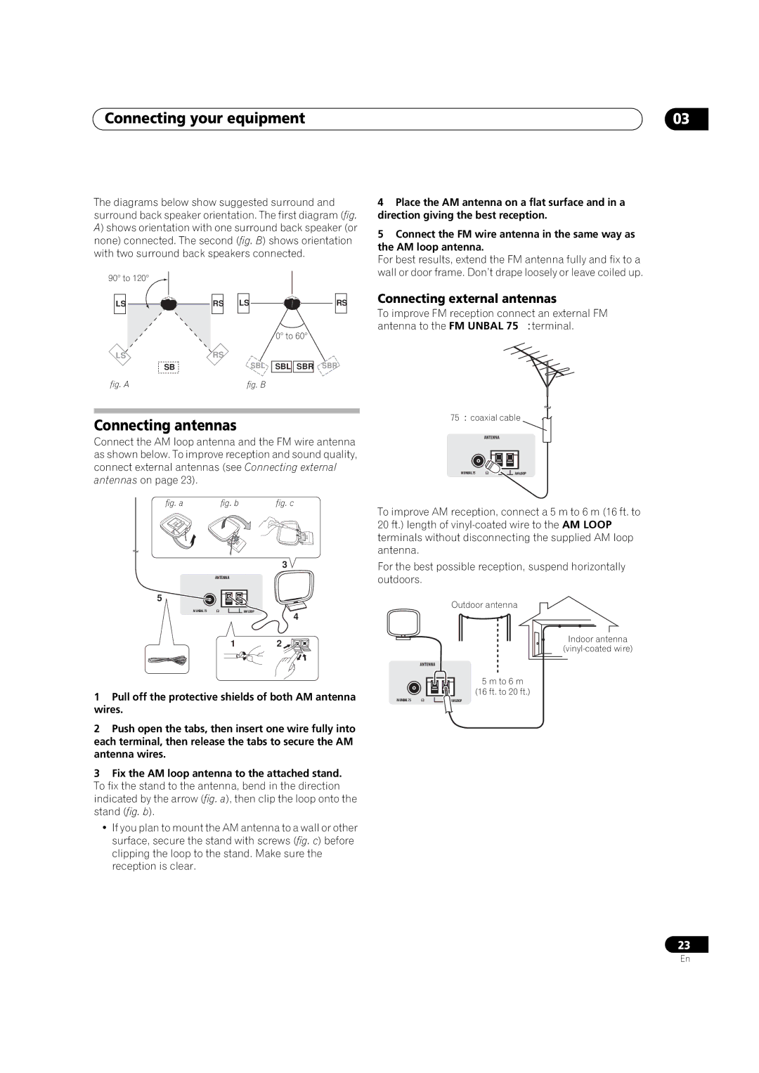
Placing the speakers
Connecting external antennas
Connecting antennas
Plug the power cord into a power outlet
Connecting your equipment Plugging in the receiver
13 14
Controls and displays
Controls and displays Chapter
Front panel
Speakers
Operating range of remote control unit
Controls and displays
Controls and displays Display
RECEIVER
Controls and displays Remote control
Receiver
TV Ctrl
SOURCE
Mute
Listening in surround sound
Listening to your system
Listening to your system Chapter
Auto playback
Pro Logic IIx Music See
Using the Advanced surround effects
Listening to your system
Listening in stereo
Selecting Mcacc presets
Listening to your system Using Front Stage Surround Advance
Using Stream Direct
Hdmi Digital Analog
Choosing the input signal
Using surround back channel processing
Auto
Using the Virtual Surround Back mode
SBch Standard Type of source
Pro Logic
DTS-HD Master Audio/DTS-HD DTS-EXPRESS encoded stereo
Using the genre synchronizing function
Mode
Pro Logic Neo6
Listening to the radio
Using the tuner
Using the tuner Chapter
Saving station presets
Abcdefghijklmnopqrstuvwxyz
Using the tuner
Naming station presets
Listening to station presets
Select the setting you want to adjust
System Setup menu
System Setup menu Chapter
Making receiver settings from the System Setup menu
Mcacc
System Setup menu
If necessary, confirm the speaker configuration OSD.1
Manual Mcacc setup
Surround back speaker setting
Fine Speaker Distance
Adjust the level of the left channel
Select ‘Fine SP Distance’ from the Manual Mcacc setup menu
Fine Channel Level
Select ‘EQ Adjust’ from the Manual Mcacc setup menu
Acoustic Calibration EQ Adjust
Select ‘Standing Wave’ from the Manual Mcacc setup menu
Adjust the parameters for the Standing Wave Control
Acoustic Calibration EQ Professional
How to use Acoustic Calibration EQ Professional
How to interpret the graphical output
Select the channels you want and adjust to your liking
Select an option and press Enter
Using Acoustic Calibration EQ Professional
Select ‘EQ Professional’, then press Enter
Data Management
Select ‘Data Management’ from the System Setup menu
Clearing Mcacc presets
Checking Mcacc preset data
Copying Mcacc preset data
Renaming Mcacc presets
Select ‘Speaker Setting’ from the Manual SP Setup menu
System Setup menu Manual speaker setup
Speaker Setting
Select ‘Manual SP Setup’, then press Enter
Channel Level
Select a setup option
Confirm your selected setup option
Adjust the level of each channel using /
Curve
Speaker Distance
Other connections Chapter
Connecting an iPod
Connecting your iPod to the receiver
Other connections
Basic playback controls
Switching the iPod controls2
Press iPod Ctrl to switch the iPod controls.3
Other connections
Basic playback controls
Other connections Connecting a USB device
Connecting your USB device to the receiver
Switch on the receiver and your TV
Compressed audio compatibility
Using XM Radio
Connecting your XM Radio receiver
Listening to XM Radio
Saving channel presets
Using XM HD Surround
Using the XM Menu
Listening to Sirius Radio
Using Sirius Radio
Connecting your SiriusConnect Tuner
Press / to select the channel preset you want
Connecting the multichannel analog inputs
Using the Sirius Menu
Sirius Menu provides additional Sirius Radio features.2
Selecting the multichannel analog inputs
Speaker B setup
Switching the speaker system
Are for the Speaker B setting only.2
Connect your speakers as shown below
Bi-wiring your speakers
Bi-amping your front speakers
Large
Other connections Connecting additional amplifiers
MULTI-ZONE listening
Making MULTI-ZONE connections
MULTI-ZONE listening options
Using the MULTI-ZONE controls
Basic MULTI-ZONE setup Zone
Surround Back System MULTI-ZONE setup Zone
Press Control
Connecting an IR receiver
MULTI-ZONE remote controls
Use the Master Volume dial to adjust the volume
Video
ANT MPX Signal SEL
Hdmi Control Chapter
Setting the Hdmi options
Setting the Hdmi Control mode
Hdmi Control
About Hdmi Control
Synchronized amp mode
Before using synchronization
Hdmi Control
Setup
Other Settings
Other Settings Chapter
Input Setup menu
Press Receiver on the remote control, then press Setup
Other Settings
Other Setup menu
Input function default and possible settings
Zone Audio Setup
Multi Channel Input Setup
Select the ‘PDP Volume Control’ setting you want
SR+ Setup for Pioneer flat panel TVs
OSD Adjustment
Select ‘SR+ Setup’ from the Other Setup menu
Press Return to confirm and exit the menu
Using other functions
Using other functions Chapter
Setting the Audio options
Press RECEIVER, then press Video Parameter
Using other functions
Setting the Video options
Use / to select the setting you want to adjust
Tune to the radio station, load the CD, video, DVD, etc
Making an audio or a video recording
Select the source you want to record
Prepare the source you want to record
Dimming the display
Using the sleep timer
Switching the speaker impedance
Checking your system settings
Press Sound Retriever to confirm
Resetting the system
Default system settings
Press the front panel Auto SURR/STREAM Direct button
Controlling the rest of your system
Setting the remote to control other components
Selecting preset codes directly
Preset code list
Controls for TVs
Controlling the rest of your system
Controls for other components
HDD
Decide which component you want to use the remote sensor
& Enter
Additional information Chapter
Troubleshooting
Power
Additional information
Additional information
SymptomRemedy
Other audio problems
Video
Settings
Display
Signal SEL button
Professional Calibration EQ graphical output
USB interface
Remote control
Hdcp Error shows
Or other setting for your component
Other setting for your component
Receiver to a component or TV with the DeepColor feature
XM radio messages
Configuration a
Configuration B
Important information regarding the Hdmi connection
Sirius radio messages
Symptom Cause Action
Dolby
Additional information Surround sound formats
DTS 96/24
Windows Media Audio 9 Professional
DTS Digital Surround
DTS Neo6
XM Ready Subscription
Additional information About XM
About Neural THX Surround
About XM Radio XM Ready Legal
ON/AUTO
Stereo 2 channel signal formats
SBch Processing Input signal format Standard Auto Surround
Pro Logic ll Movie Pro Logic ll Music Pro Logic ll Game
Pro Logic ll Movie
Pro Logic ll Music Pro Logic ll Game
PRO Logic
Multichannel signal formats
PCM
Dolby Digital Surround
Direct Pure Direct
Additional information Specifications
Additional information Cleaning the unit
Decibel Level Example
To establish a safe level
Once you have established a comfortable sound level
Pioneer Electronics DE Mexico S.A. DE C.V
Pioneer Electronics USA INC
Pioneer Electronics of CANADA, INC
Pioneer Europe NV