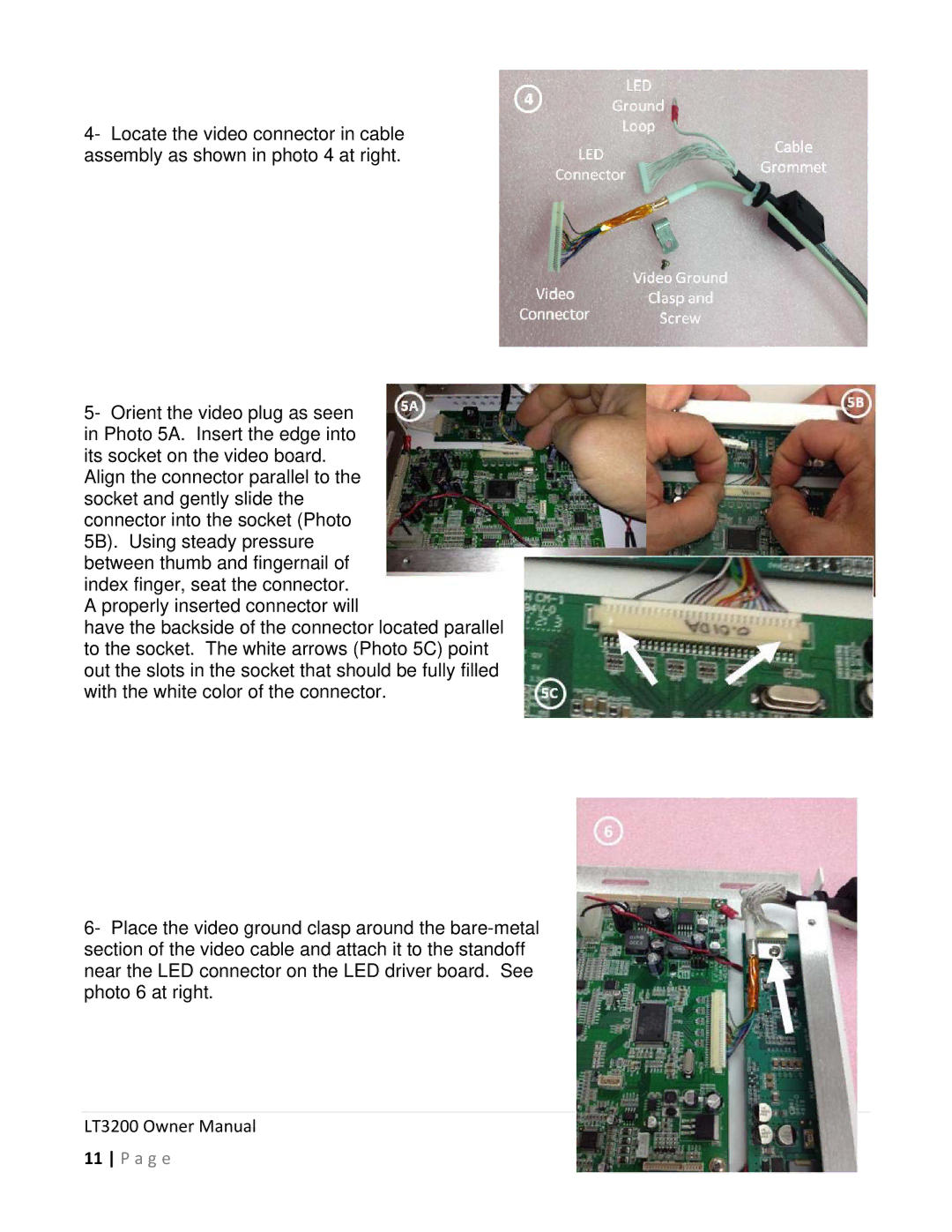
4- Locate the video connector in cable assembly as shown in photo 4 at right.
5- Orient the video plug as seen in Photo 5A. Insert the edge into its socket on the video board.
Align the connector parallel to the socket and gently slide the connector into the socket (Photo 5B). Using steady pressure between thumb and fingernail of index finger, seat the connector. A properly inserted connector will
have the backside of the connector located parallel to the socket. The white arrows (Photo 5C) point out the slots in the socket that should be fully filled with the white color of the connector.
6- Place the video ground clasp around the
