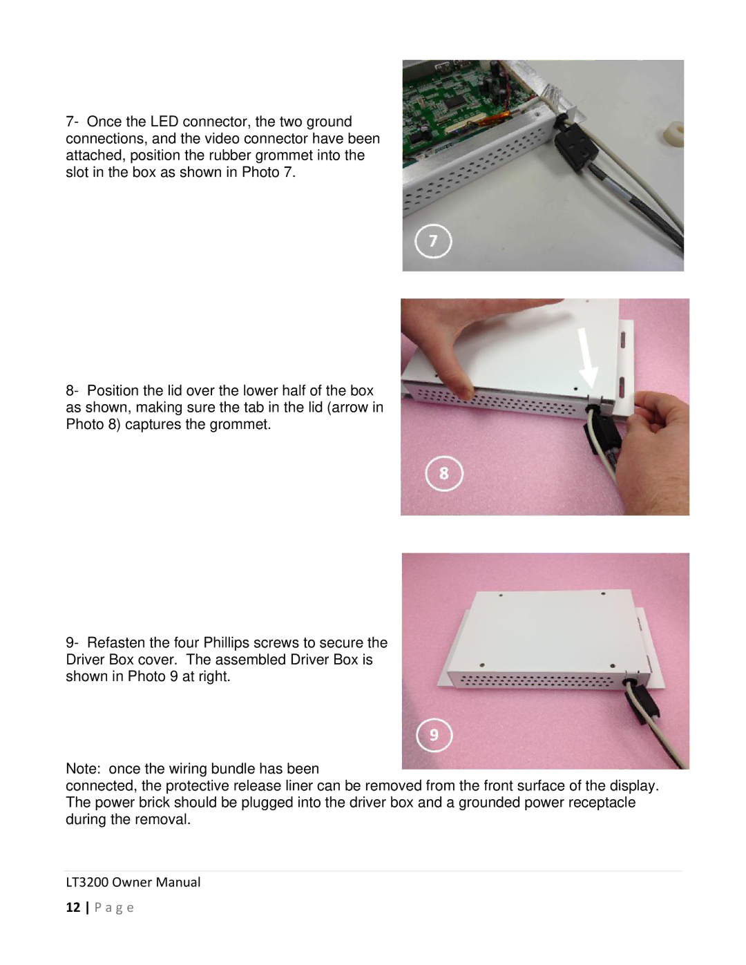
7- Once the LED connector, the two ground connections, and the video connector have been attached, position the rubber grommet into the slot in the box as shown in Photo 7.
8- Position the lid over the lower half of the box as shown, making sure the tab in the lid (arrow in Photo 8) captures the grommet.
9- Refasten the four Phillips screws to secure the Driver Box cover. The assembled Driver Box is shown in Photo 9 at right.
Note: once the wiring bundle has been
connected, the protective release liner can be removed from the front surface of the display. The power brick should be plugged into the driver box and a grounded power receptacle during the removal.