VI. Connecting the Driver Box
The LT3200 is shipped with the wiring bundle disconnected from the Driver Box so the free end of the bundle can be routed in the enclosure as part of the assembly process. This section describes how to connect the wiring bundle to the Driver Box. You will need a small (#1) Phillips screwdriver.
Note: It is important to follow the instructions carefully and observe safe ESD practices, especially if the assembly is taking place away from a grounded workbench.
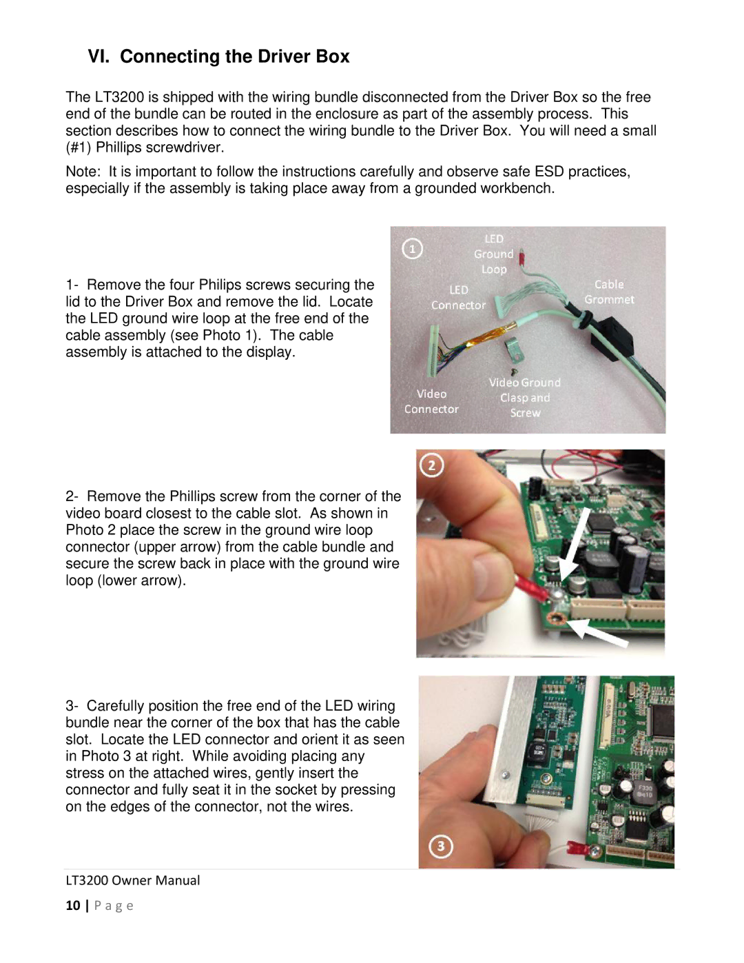
1- Remove the four Philips screws securing the lid to the Driver Box and remove the lid. Locate the LED ground wire loop at the free end of the cable assembly (see Photo 1). The cable assembly is attached to the display.
2- Remove the Phillips screw from the corner of the video board closest to the cable slot. As shown in Photo 2 place the screw in the ground wire loop connector (upper arrow) from the cable bundle and secure the screw back in place with the ground wire loop (lower arrow).
3- Carefully position the free end of the LED wiring bundle near the corner of the box that has the cable slot. Locate the LED connector and orient it as seen in Photo 3 at right. While avoiding placing any stress on the attached wires, gently insert the connector and fully seat it in the socket by pressing on the edges of the connector, not the wires.