![]() C
C
C
B
A
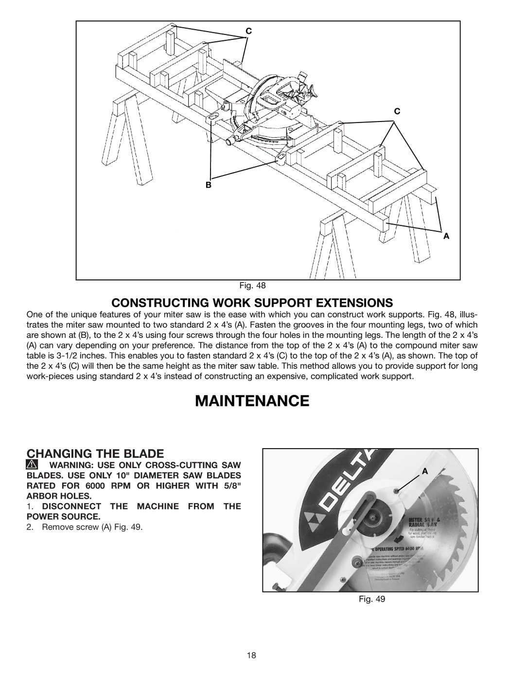
Fig. 48
CONSTRUCTING WORK SUPPORT EXTENSIONS
One of the unique features of your miter saw is the ease with which you can construct work supports. Fig. 48, illus- trates the miter saw mounted to two standard 2 x 4’s (A). Fasten the grooves in the four mounting legs, two of which are shown at (B), to the 2 x 4’s using four screws through the four holes in the mounting legs. The length of the 2 x 4’s
(A)can vary depending on your preference. The distance from the top of the 2 x 4’s (A) to the compound miter saw table is
MAINTENANCE
CHANGING THE BLADE
![]() WARNING: USE ONLY
WARNING: USE ONLY
ARBOR HOLES.
1.DISCONNECT THE MACHINE FROM THE POWER SOURCE.
2.Remove screw (A) Fig. 49.
A
Fig. 49
18