OPERATING CONTROLS
STARTING AND
STOPPING MACHINE
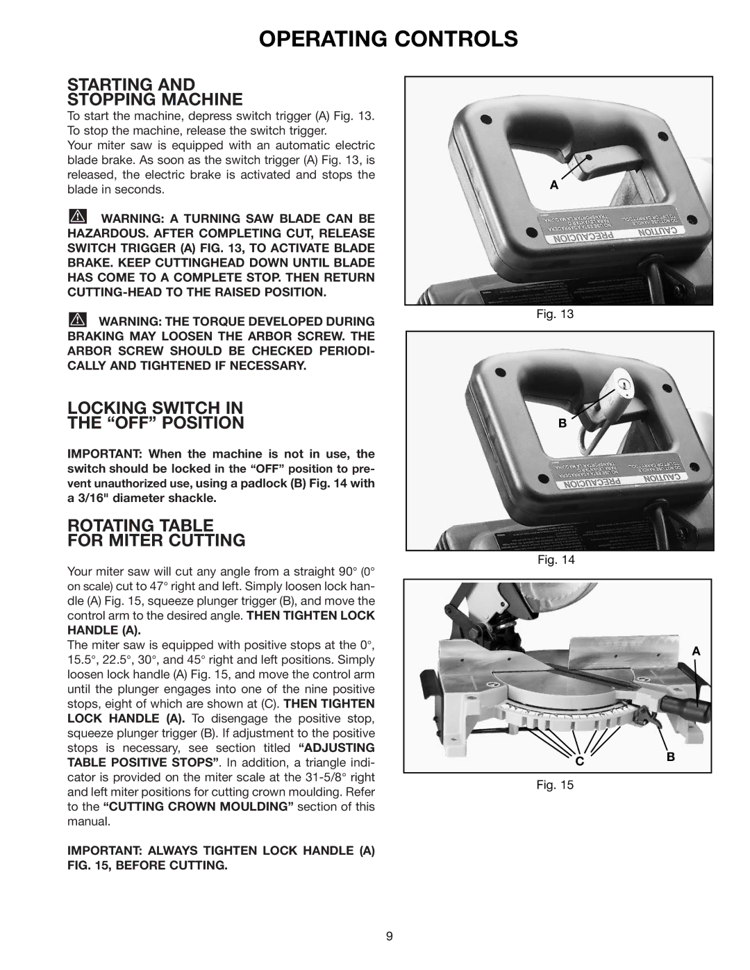
To start the machine, depress switch trigger (A) Fig. 13. To stop the machine, release the switch trigger.
Your miter saw is equipped with an automatic electric blade brake. As soon as the switch trigger (A) Fig. 13, is released, the electric brake is activated and stops the blade in seconds.
![]() WARNING: A TURNING SAW BLADE CAN BE HAZARDOUS. AFTER COMPLETING CUT, RELEASE SWITCH TRIGGER (A) FIG. 13, TO ACTIVATE BLADE BRAKE. KEEP CUTTINGHEAD DOWN UNTIL BLADE HAS COME TO A COMPLETE STOP. THEN RETURN
WARNING: A TURNING SAW BLADE CAN BE HAZARDOUS. AFTER COMPLETING CUT, RELEASE SWITCH TRIGGER (A) FIG. 13, TO ACTIVATE BLADE BRAKE. KEEP CUTTINGHEAD DOWN UNTIL BLADE HAS COME TO A COMPLETE STOP. THEN RETURN
![]() WARNING: THE TORQUE DEVELOPED DURING BRAKING MAY LOOSEN THE ARBOR SCREW. THE ARBOR SCREW SHOULD BE CHECKED PERIODI- CALLY AND TIGHTENED IF NECESSARY.
WARNING: THE TORQUE DEVELOPED DURING BRAKING MAY LOOSEN THE ARBOR SCREW. THE ARBOR SCREW SHOULD BE CHECKED PERIODI- CALLY AND TIGHTENED IF NECESSARY.
LOCKING SWITCH IN
THE “OFF” POSITION
IMPORTANT: When the machine is not in use, the switch should be locked in the “OFF” position to pre- vent unauthorized use, using a padlock (B) Fig. 14 with a 3/16" diameter shackle.
ROTATING TABLE
FOR MITER CUTTING
Your miter saw will cut any angle from a straight 90° (0° on scale) cut to 47° right and left. Simply loosen lock han- dle (A) Fig. 15, squeeze plunger trigger (B), and move the control arm to the desired angle. THEN TIGHTEN LOCK
HANDLE (A).
The miter saw is equipped with positive stops at the 0°, 15.5°, 22.5°, 30°, and 45° right and left positions. Simply loosen lock handle (A) Fig. 15, and move the control arm until the plunger engages into one of the nine positive stops, eight of which are shown at (C). THEN TIGHTEN LOCK HANDLE (A). To disengage the positive stop, squeeze plunger trigger (B). If adjustment to the positive stops is necessary, see section titled “ADJUSTING TABLE POSITIVE STOPS”. In addition, a triangle indi- cator is provided on the miter scale at the
IMPORTANT: ALWAYS TIGHTEN LOCK HANDLE (A) FIG. 15, BEFORE CUTTING.
A
Fig. 13
B
Fig. 14
A
CB
Fig. 15
9