CUTTING
CROWN MOULDING
One of the many features of your saw is the ease of cut- ting crown moulding. The following is an example of cut- ting both inside and outside corners on 52/38° wall angle crown moulding. NOTE: When cutting 45° wall angle crown moulding the following procedure for inside and outside corners is the same with the exception that the bevel position will always be at 30° and the miter position will be
1.Move the table to the
2.Tilt the saw blade to the
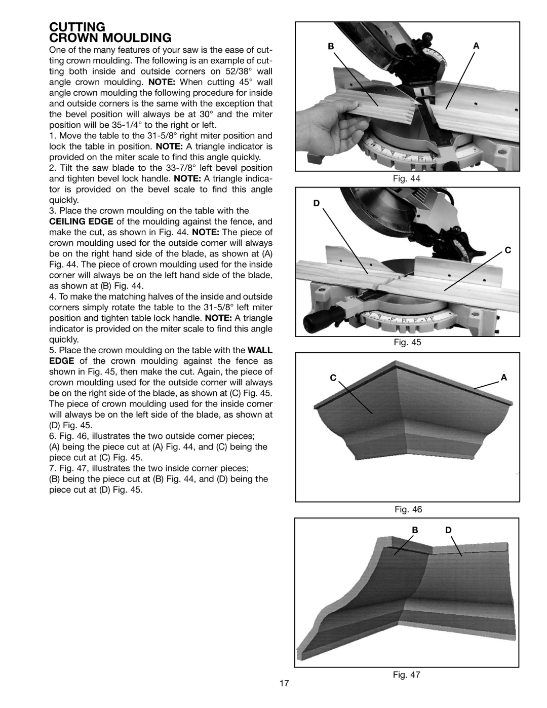
3.Place the crown moulding on the table with the CEILING EDGE of the moulding against the fence, and make the cut, as shown in Fig. 44. NOTE: The piece of crown moulding used for the outside corner will always be on the right hand side of the blade, as shown at (A) Fig. 44. The piece of crown moulding used for the inside corner will always be on the left hand side of the blade, as shown at (B) Fig. 44.
4.To make the matching halves of the inside and outside corners simply rotate the table to the
5.Place the crown moulding on the table with the WALL EDGE of the crown moulding against the fence as shown in Fig. 45, then make the cut. Again, the piece of crown moulding used for the outside corner will always be on the right side of the blade, as shown at (C) Fig. 45. The piece of crown moulding used for the inside corner will always be on the left side of the blade, as shown at
(D) Fig. 45.
6.Fig. 46, illustrates the two outside corner pieces;
(A)being the piece cut at (A) Fig. 44, and (C) being the piece cut at (C) Fig. 45.
7. Fig. 47, illustrates the two inside corner pieces;
(B)being the piece cut at (B) Fig. 44, and (D) being the piece cut at (D) Fig. 45.
BA
Fig. 44
D
C
Fig. 45
CA
Fig. 46
B D
Fig. 47
17