INSTALLING SWITCH
AND MOTOR CORD
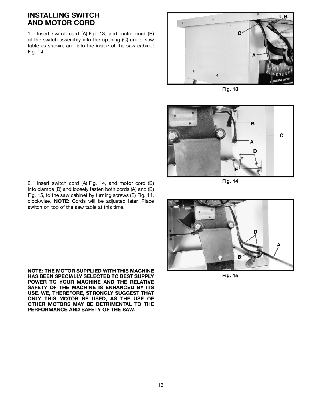
1.Insert switch cord (A) Fig. 13, and motor cord (B) of the switch assembly into the opening (C) under saw table as shown, and into the inside of the saw cabinet Fig. 14.
2.Insert switch cord (A) Fig. 14, and motor cord (B) into clamps (D) and loosely fasten both cords (A) and (B) Fig. 15, to the saw cabinet by turning screws (E) Fig. 14, clockwise. NOTE: Cords will be adjusted later. Place switch on top of the saw table at this time.
NOTE: THE MOTOR SUPPLIED WITH THIS MACHINE HAS BEEN SPECIALLY SELECTED TO BEST SUPPLY POWER TO YOUR MACHINE AND THE RELATIVE SAFETY OF THE MACHINE IS ENHANCED BY ITS USE. WE, THEREFORE, STRONGLY SUGGEST THAT ONLY THIS MOTOR BE USED, AS THE USE OF OTHER MOTORS MAY BE DETRIMENTAL TO THE PERFORMANCE AND SAFETY OF THE SAW.
B
C
A![]()
Fig. 13
B
C
A
D
E![]()
Fig. 14
D
A
B
Fig. 15
13