BLADE GUARD AND SPLITTER ASSEMBLY AND ALIGNMENT
1.DISCONNECT MACHINE FROM POWER SOURCE.
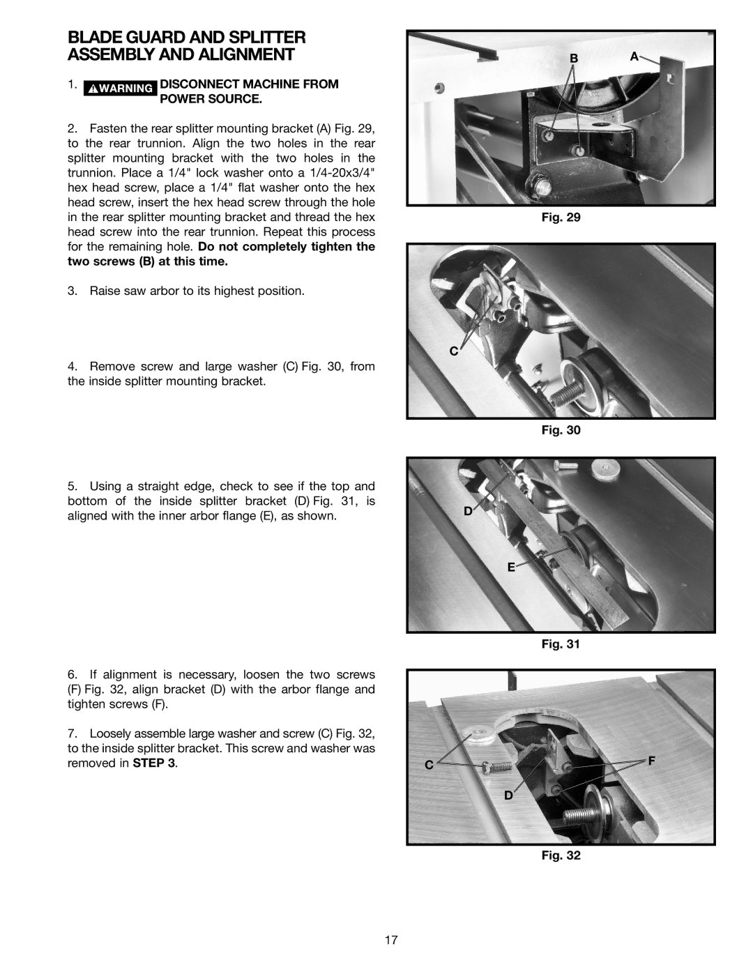
2.Fasten the rear splitter mounting bracket (A) Fig. 29, to the rear trunnion. Align the two holes in the rear splitter mounting bracket with the two holes in the trunnion. Place a 1/4" lock washer onto a
3.Raise saw arbor to its highest position.
4.Remove screw and large washer (C) Fig. 30, from the inside splitter mounting bracket.
5.Using a straight edge, check to see if the top and bottom of the inside splitter bracket (D) Fig. 31, is aligned with the inner arbor flange (E), as shown.
6.If alignment is necessary, loosen the two screws
(F) Fig. 32, align bracket (D) with the arbor flange and tighten screws (F).
7.Loosely assemble large washer and screw (C) Fig. 32, to the inside splitter bracket. This screw and washer was removed in STEP 3.
B A![]()
Fig. 29
C
Fig. 30
D
E![]()
Fig. 31
C ![]()
![]() F
F
D
Fig. 32
17