MOVING CUTTINGHEAD TO THE UP POSITION
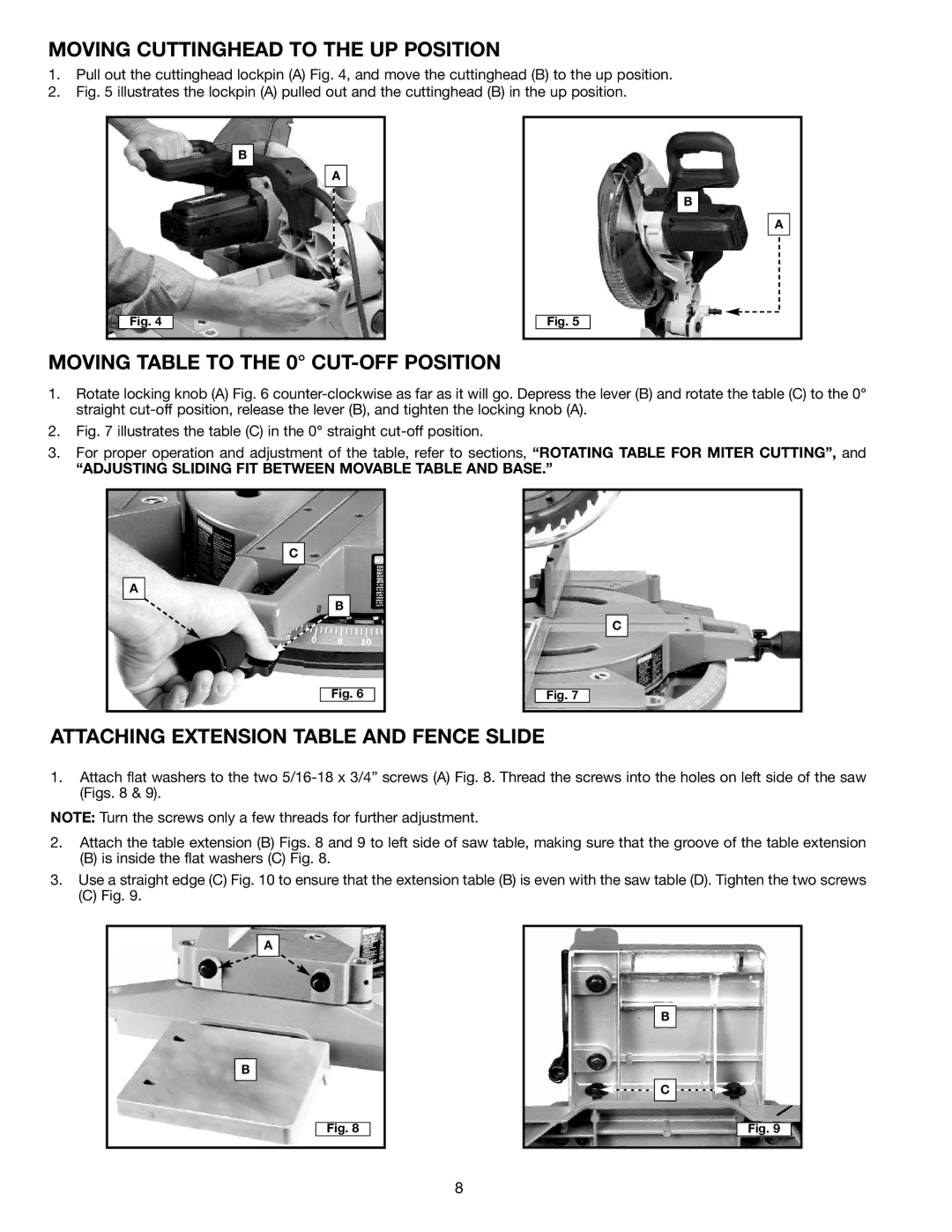
1.Pull out the cuttinghead lockpin (A) Fig. 4, and move the cuttinghead (B) to the up position.
2.Fig. 5 illustrates the lockpin (A) pulled out and the cuttinghead (B) in the up position.
B
A
B
A
Fig. 4
Fig. 5
MOVING TABLE TO THE 0° CUT-OFF POSITION
1.Rotate locking knob (A) Fig. 6
2.Fig. 7 illustrates the table (C) in the 0° straight cut-off position.
3.For proper operation and adjustment of the table, refer to sections, “ROTATING TABLE FOR MITER CUTTING”, and
“ADJUSTING SLIDING FIT BETWEEN MOVABLE TABLE AND BASE.”
C
A
B
C
Fig. 6
Fig. 7
ATTACHING EXTENSION TABLE AND FENCE SLIDE
1.Attach flat washers to the two
NOTE: Turn the screws only a few threads for further adjustment.
2.Attach the table extension (B) Figs. 8 and 9 to left side of saw table, making sure that the groove of the table extension
(B)is inside the flat washers (C) Fig. 8.
3.Use a straight edge (C) Fig. 10 to ensure that the extension table (B) is even with the saw table (D). Tighten the two screws
(C)Fig. 9.
A
B
Fig. 8
B
![]()
![]()
![]() C
C ![]()
![]()
![]()
Fig. 9
8
