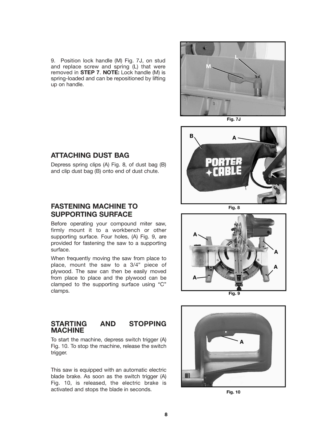
9.Position lock handle (M) Fig. 7J, on stud and replace screw and spring (L) that were removed in STEP 7. NOTE: Lock handle (M) is
ATTACHING DUST BAG
Depress spring clips (A) Fig. 8, of dust bag (B) and clip dust bag (B) onto end of dust chute.
FASTENING MACHINE TO SUPPORTING SURFACE
Before operating your compound miter saw, firmly mount it to a workbench or other supporting surface. Four holes, (A) Fig. 9, are provided for fastening the saw to a supporting surface.
When frequently moving the saw from place to place, mount the saw to a 3/4” piece of plywood. The saw can then be easily moved from place to place and the plywood can be clamped to the supporting surface using “C” clamps.
L
M
Fig. 7J
BA
Fig. 8
A
A
A
A![]()
Fig. 9
STARTING AND STOPPING MACHINE
To start the machine, depress switch trigger (A) Fig. 10. To stop the machine, release the switch trigger.
This saw is equipped with an automatic electric blade brake. As soon as the switch trigger (A) Fig. 10, is released, the electric brake is activated and stops the blade in seconds.
A
Fig. 10
8
