ATTACHING THE MOTOR TO THE ROUTER
1.CAUTION: DISCONNECT TOOL FROM POWER SOURCE.
2.Open the clamp (A) Fig. 1, and set the power unit in the base unit.
3.Align the lower pin of the motor unit (B) Fig. 1 with the groove in the base.
4.Rotate the motor unit CLOCKWISE into the base until the upper guide pins are set in the groove of the base.
5.Close the clamp.
ADJUSTING DEPTH OF CUT
1.CAUTION: DISCONNECT TOOL FROM POWER SOURCE.
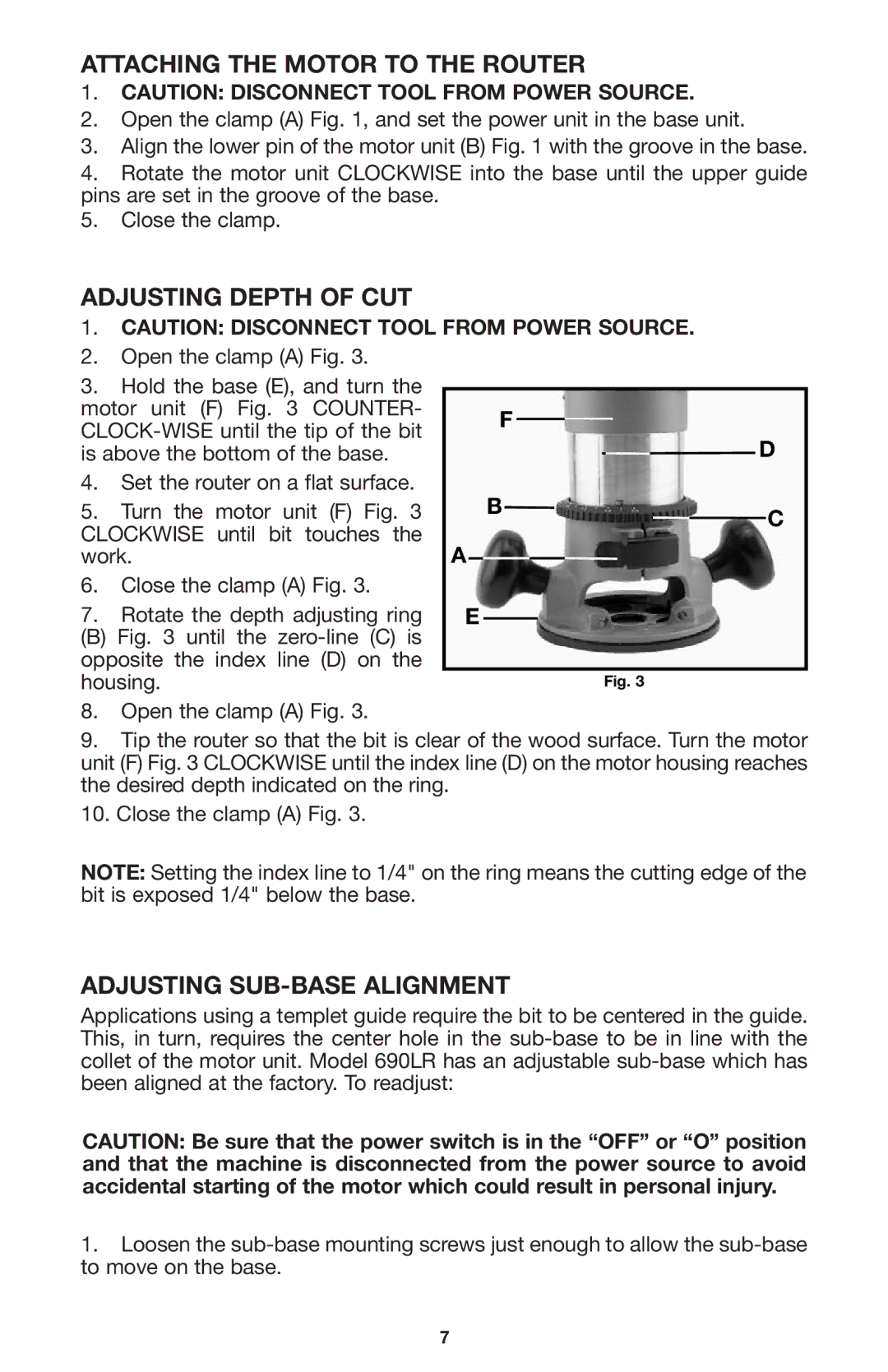
2.Open the clamp (A) Fig. 3.
3.Hold the base (E), and turn the motor unit (F) Fig. 3 COUNTER-
4.Set the router on a flat surface.
5.Turn the motor unit (F) Fig. 3 CLOCKWISE until bit touches the work.
6.Close the clamp (A) Fig. 3.
7.Rotate the depth adjusting ring
(B) Fig. 3 until the zero-line (C) is opposite the index line (D) on the housing.
8.Open the clamp (A) Fig. 3.
F
D
B
C
A ![]()
E
Fig. 3
9.Tip the router so that the bit is clear of the wood surface. Turn the motor unit (F) Fig. 3 CLOCKWISE until the index line (D) on the motor housing reaches the desired depth indicated on the ring.
10.Close the clamp (A) Fig. 3.
NOTE: Setting the index line to 1/4" on the ring means the cutting edge of the bit is exposed 1/4" below the base.
ADJUSTING SUB-BASE ALIGNMENT
Applications using a templet guide require the bit to be centered in the guide. This, in turn, requires the center hole in the
CAUTION: Be sure that the power switch is in the “OFF” or “O” position and that the machine is disconnected from the power source to avoid accidental starting of the motor which could result in personal injury.
1.Loosen the
7