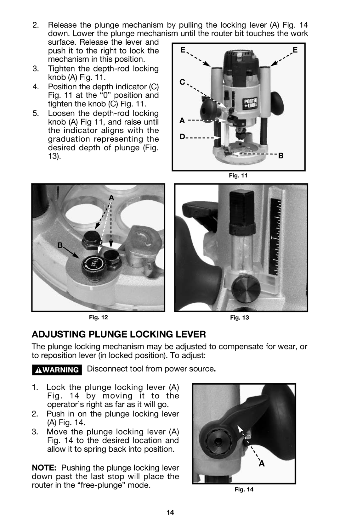
2.Release the plunge mechanism by pulling the locking lever (A) Fig. 14 down. Lower the plunge mechanism until the router bit touches the work
| surface. Release the lever and |
|
|
| E | E | |
| push it to the right to lock the | ||
| mechanism in this position. |
|
|
3. | Tighten the |
|
|
| knob (A) Fig. 11. | C |
|
4. | Position the depth indicator (C) |
| |
|
| ||
| Fig. 11 at the “0” position and |
|
|
tighten the knob (C) Fig. 11.
5.Loosen the depth-rod locking
knob (A) Fig 11, and raise until | A | ||||
the indicator aligns with the | D |
|
|
|
|
graduation representing the |
|
|
|
| |
|
| ||||
desired depth of plunge (Fig. |
|
|
|
| B |
13). |
|
|
|
| |
Fig. 11
A
B
Fig. 12 | Fig. 13 |
ADJUSTING PLUNGE LOCKING LEVER
The plunge locking mechanism may be adjusted to compensate for wear, or to reposition lever (in locked position). To adjust:
Disconnect tool from power source.
1.Lock the plunge locking lever (A) Fig. 14 by moving it to the operator’s right as far as it will go.
2.Push in on the plunge locking lever
(A) Fig. 14.
3.Move the plunge locking lever (A) Fig. 14 to the desired location and allow it to spring back into position.
NOTE: Pushing the plunge locking lever down past the last stop will place the router in the
A
Fig. 14
14
