FUNCTIONAL DESCRIPTION
FOREWORD
ASSEMBLY
NOTE: This tool is shipped completely assembled. No assembly time or tools are required.
SELECTING THE BIT
The 891 series of routers accommodates bits with 1/4“ and 1/2“ diameter shanks. A collet is also available that will accommodate bits with 3/8“ diameter shanks.
![]() Use router bits with a diameter larger than
Use router bits with a diameter larger than
![]() Disconnect tool from power source when preparing the router for use, making adjustments, and when router is not in use.
Disconnect tool from power source when preparing the router for use, making adjustments, and when router is not in use.
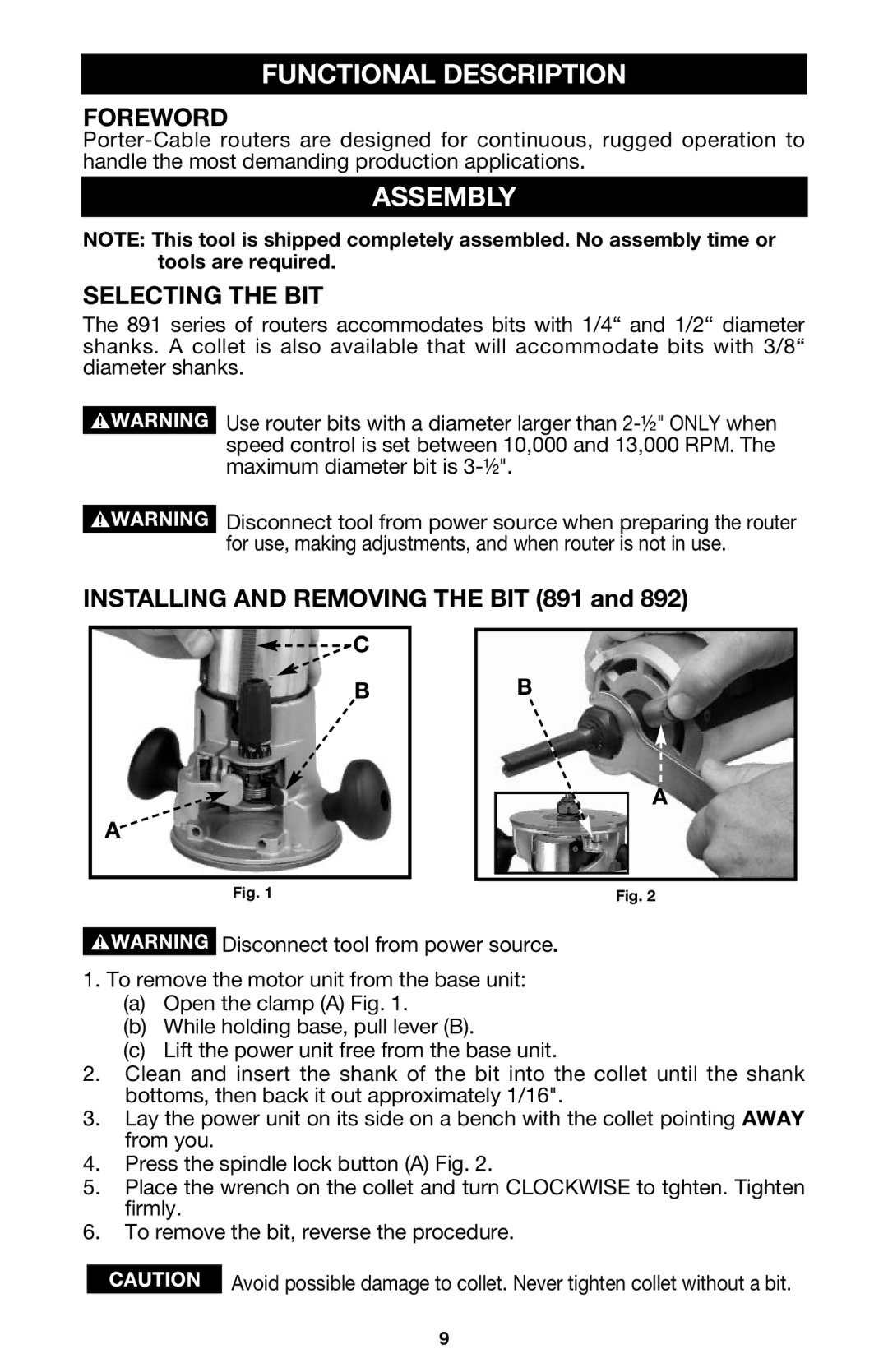
INSTALLING AND REMOVING THE BIT (891 and 892)
![]()
![]() C
C
B
A
B
A
Fig. 1 | Fig. 2 |
![]() Disconnect tool from power source.
Disconnect tool from power source.
1.To remove the motor unit from the base unit:
(a)Open the clamp (A) Fig. 1.
(b)While holding base, pull lever (B).
(c)Lift the power unit free from the base unit.
2.Clean and insert the shank of the bit into the collet until the shank bottoms, then back it out approximately 1/16".
3.Lay the power unit on its side on a bench with the collet pointing AWAY from you.
4.Press the spindle lock button (A) Fig. 2.
5.Place the wrench on the collet and turn CLOCKWISE to tghten. Tighten firmly.
6.To remove the bit, reverse the procedure.
![]() Avoid possible damage to collet. Never tighten collet without a bit.
Avoid possible damage to collet. Never tighten collet without a bit.
9