DESCRIPTION OF OPERATION
Drain Valve (not shown): The drain valve is located at the base of the air tank and is used to drain condensation at the end of each use.
Motor Thermal Overload Protector (not shown): The electric motor has an automatic thermal overload protector. If the motor overheats for any reason, the thermal overload protector will shut off the motor. The motor must be allowed to cool before restarting.
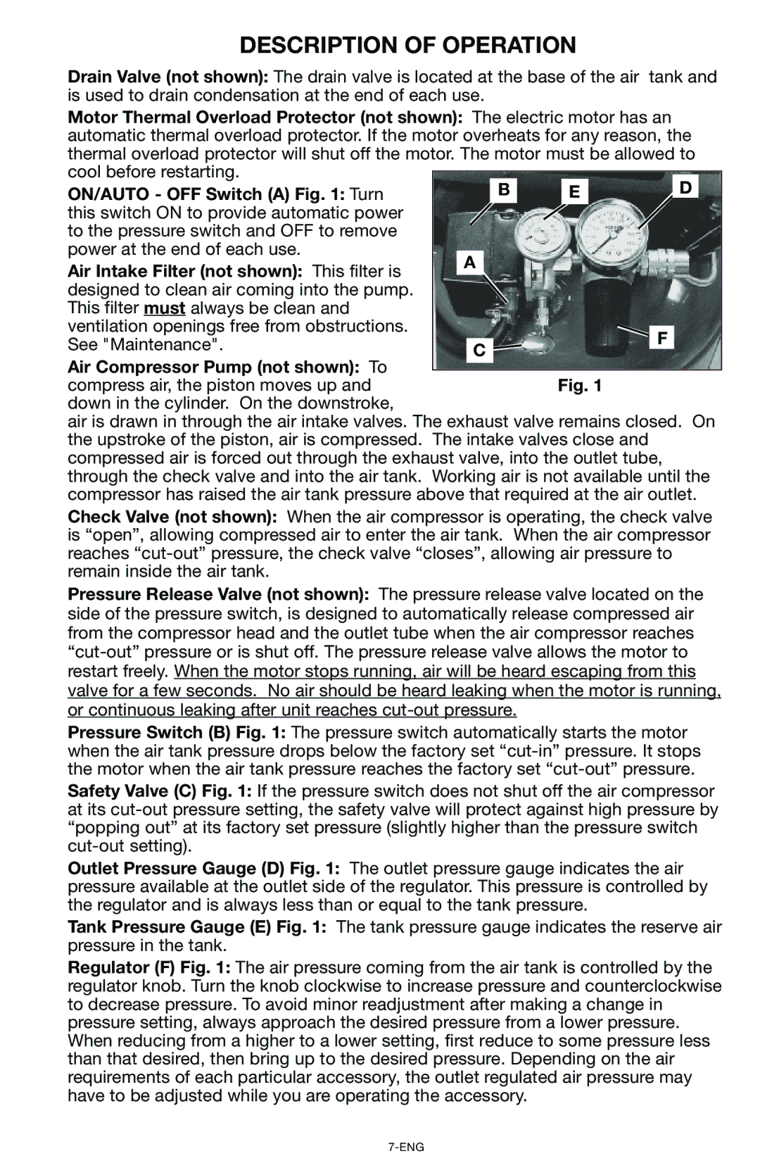
ON/AUTO - OFF Switch (A) Fig. 1: Turn |
|
| B |
| E |
|
| D |
this switch ON to provide automatic power |
|
|
|
|
|
|
|
|
to the pressure switch and OFF to remove |
|
|
|
|
|
|
|
|
power at the end of each use. |
|
|
|
|
|
|
|
|
A |
|
|
|
|
|
|
| |
Air Intake Filter (not shown): This filter is |
|
|
|
|
|
|
| |
|
|
|
|
|
|
|
| |
|
|
|
|
|
|
|
| |
designed to clean air coming into the pump. |
|
|
|
|
|
|
|
|
This filter must always be clean and |
|
|
|
|
|
|
|
|
ventilation openings free from obstructions. |
|
|
|
|
|
|
|
|
|
|
|
|
|
| F |
| |
See "Maintenance". | C |
|
|
| ||||
|
|
|
| |||||
|
|
|
|
| ||||
Air Compressor Pump (not shown): To compress air, the piston moves up and down in the cylinder. On the downstroke,
air is drawn in through the air intake valves. The exhaust valve remains closed. On the upstroke of the piston, air is compressed. The intake valves close and compressed air is forced out through the exhaust valve, into the outlet tube, through the check valve and into the air tank. Working air is not available until the compressor has raised the air tank pressure above that required at the air outlet.
Check Valve (not shown): When the air compressor is operating, the check valve is “open”, allowing compressed air to enter the air tank. When the air compressor reaches
Pressure Release Valve (not shown): The pressure release valve located on the side of the pressure switch, is designed to automatically release compressed air from the compressor head and the outlet tube when the air compressor reaches
Pressure Switch (B) Fig. 1: The pressure switch automatically starts the motor when the air tank pressure drops below the factory set
Safety Valve (C) Fig. 1: If the pressure switch does not shut off the air compressor at its
Outlet Pressure Gauge (D) Fig. 1: The outlet pressure gauge indicates the air pressure available at the outlet side of the regulator. This pressure is controlled by the regulator and is always less than or equal to the tank pressure.
Tank Pressure Gauge (E) Fig. 1: The tank pressure gauge indicates the reserve air pressure in the tank.
Regulator (F) Fig. 1: The air pressure coming from the air tank is controlled by the regulator knob. Turn the knob clockwise to increase pressure and counterclockwise to decrease pressure. To avoid minor readjustment after making a change in pressure setting, always approach the desired pressure from a lower pressure. When reducing from a higher to a lower setting, first reduce to some pressure less than that desired, then bring up to the desired pressure. Depending on the air requirements of each particular accessory, the outlet regulated air pressure may have to be adjusted while you are operating the accessory.