STAND ASSEMBLY
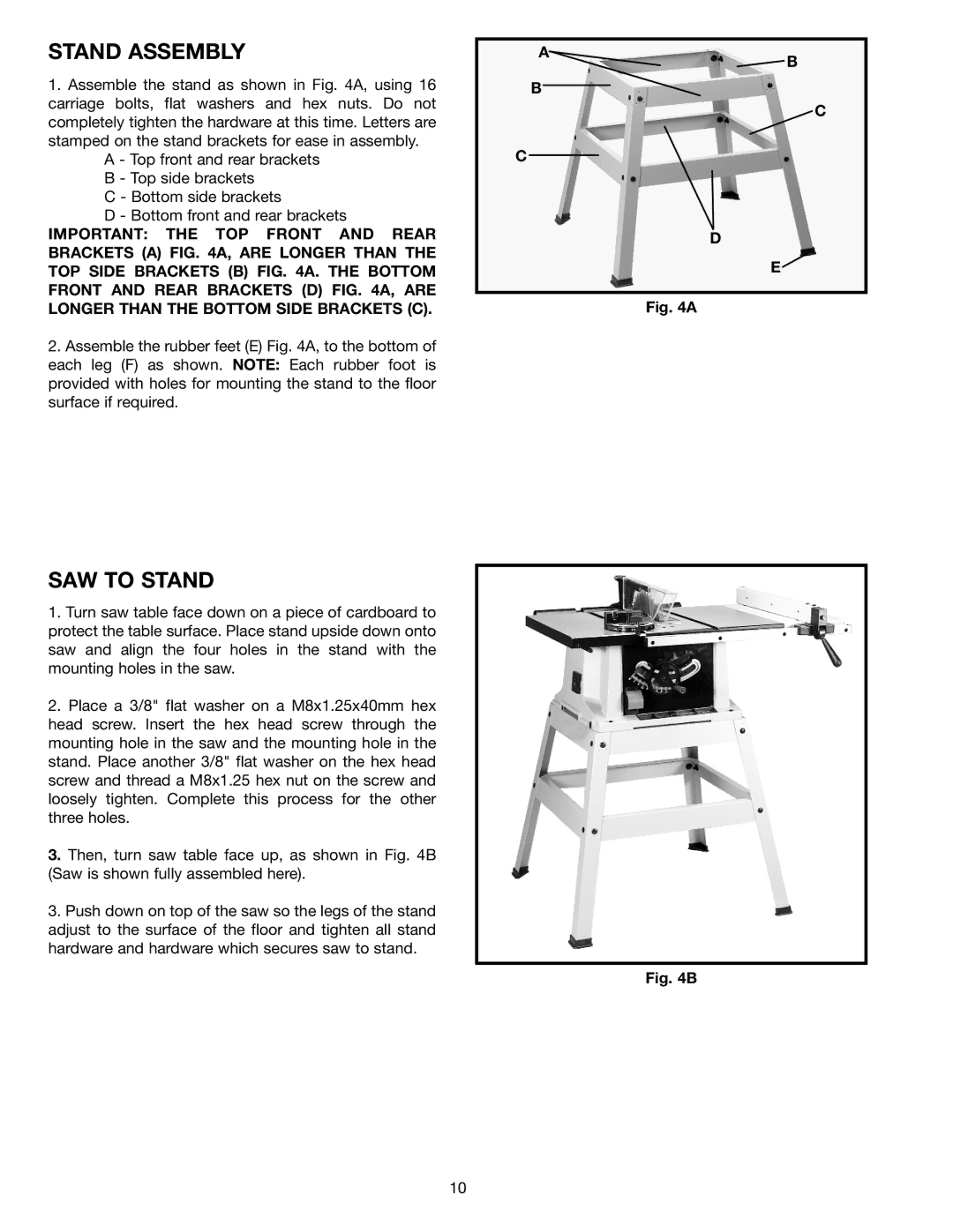
1. Assemble the stand as shown in Fig. 4A, using 16 |
carriage bolts, flat washers and hex nuts. Do not |
completely tighten the hardware at this time. Letters are |
stamped on the stand brackets for ease in assembly. |
A - Top front and rear brackets |
B - Top side brackets |
C - Bottom side brackets |
D - Bottom front and rear brackets |
A
B
C
![]() B
B
![]() C
C
IMPORTANT: THE TOP FRONT AND REAR |
BRACKETS (A) FIG. 4A, ARE LONGER THAN THE |
TOP SIDE BRACKETS (B) FIG. 4A. THE BOTTOM |
FRONT AND REAR BRACKETS (D) FIG. 4A, ARE |
LONGER THAN THE BOTTOM SIDE BRACKETS (C). |
2. Assemble the rubber feet (E) Fig. 4A, to the bottom of |
each leg (F) as shown. NOTE: Each rubber foot is |
provided with holes for mounting the stand to the floor |
surface if required. |
D
E![]()
Fig. 4A
SAW TO STAND
1.Turn saw table face down on a piece of cardboard to protect the table surface. Place stand upside down onto saw and align the four holes in the stand with the mounting holes in the saw.
2.Place a 3/8" flat washer on a M8x1.25x40mm hex head screw. Insert the hex head screw through the mounting hole in the saw and the mounting hole in the stand. Place another 3/8" flat washer on the hex head screw and thread a M8x1.25 hex nut on the screw and loosely tighten. Complete this process for the other three holes.
3.Then, turn saw table face up, as shown in Fig. 4B (Saw is shown fully assembled here).
3.Push down on top of the saw so the legs of the stand adjust to the surface of the floor and tighten all stand hardware and hardware which secures saw to stand.
Fig. 4B
10