RIP FENCE
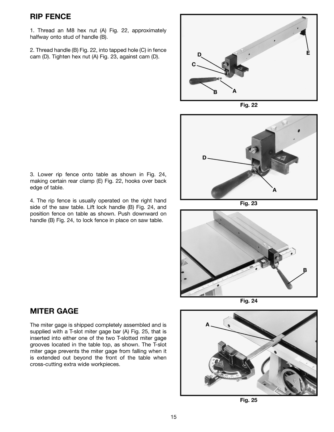
1.Thread an M8 hex nut (A) Fig. 22, approximately halfway onto stud of handle (B).
2.Thread handle (B) Fig. 22, into tapped hole (C) in fence cam (D). Tighten hex nut (A) Fig. 23, against cam (D).
3.Lower rip fence onto table as shown in Fig. 24, making certain rear clamp (E) Fig. 22, hooks over back edge of table.
4.The rip fence is usually operated on the right hand side of the saw table. Lift lock handle (B) Fig. 24, and position fence on table as shown. Push downward on handle (B) Fig. 24, to lock fence in place on saw table.
MITER GAGE
The miter gage is shipped completely assembled and is supplied with a
DE
C
B A
Fig. 22
D
A
Fig. 23
B
Fig. 24
A
Fig. 25
15