E. SPECIAL ADJUSTMENTS
1.Paper near end sensor
If the paper near end sensor is installed in the printer and enabled, a
fine tuning on the position of the paper near end sensor may be
required for different outer diameter
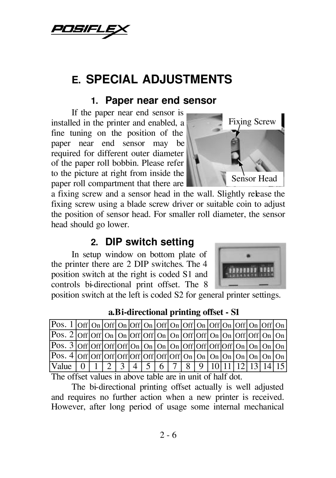
of the paper roll bobbin. Please refer to the picture at right from inside the
paper roll compartment that there are
a fixing screw and a sensor head in the wall. Slightly release the fixing screw using a blade screw driver or suitable coin to adjust the position of sensor head. For smaller roll diameter, the sensor head should go lower.
2.DIP switch setting
In setup window on bottom plate of the printer there are 2 DIP switches. The 4 position switch at the right is coded S1 and controls
position switch at the left is coded S2 for general printer settings.
a.Bi-directional printing offset - S1
Pos. 1 | Off | On | Off | On | Off | On | Off | On | Off | On | Off | On | Off | On | Off | On |
Pos. 2 | Off | Off | On | On | Off | Off | On | On | Off | Off | On | On | Off | Off | On | On |
Pos. 3 | Off | Off | Off | Off | On | On | On | On | Off | Off | Off | Off | On | On | On | On |
Pos. 4 | Off | Off | Off | Off | Off | Off | Off | Off | On | On | On | On | On | On | On | On |
Value | 0 | 1 | 2 | 3 | 4 | 5 | 6 | 7 | 8 | 9 | 10 | 11 | 12 | 13 | 14 | 15 |
The offset values in above table are in unit of half dot.
The
2 - 6