preferred for a permanent device like a bar code scanner in POS business.
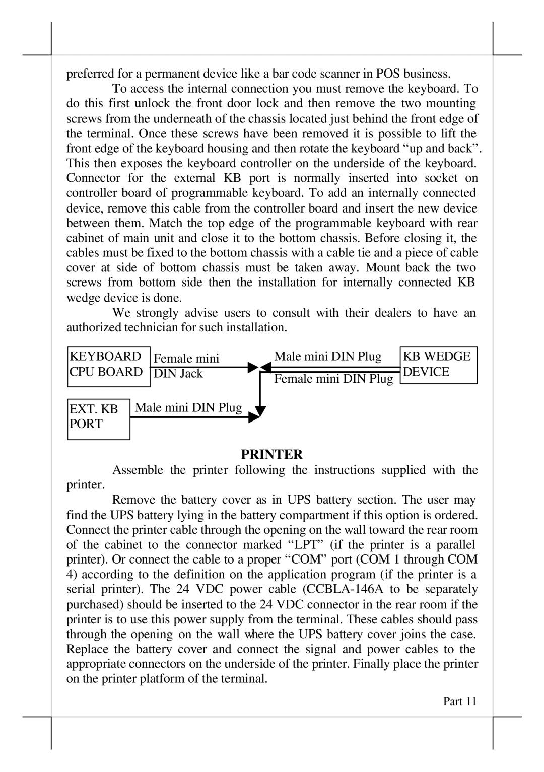
To access the internal connection you must remove the keyboard. To do this first unlock the front door lock and then remove the two mounting screws from the underneath of the chassis located just behind the front edge of the terminal. Once these screws have been removed it is possible to lift the front edge of the keyboard housing and then rotate the keyboard “up and back”. This then exposes the keyboard controller on the underside of the keyboard. Connector for the external KB port is normally inserted into socket on controller board of programmable keyboard. To add an internally connected device, remove this cable from the controller board and insert the new device between them. Match the top edge of the programmable keyboard with rear cabinet of main unit and close it to the bottom chassis. Before closing it, the cables must be fixed to the bottom chassis with a cable tie and a piece of cable cover at side of bottom chassis must be taken away. Mount back the two screws from bottom side then the installation for internally connected KB wedge device is done.
We strongly advise users to consult with their dealers to have an authorized technician for such installation.
KEYBOARD | Female mini |
CPU BOARD |
|
DIN Jack | |
|
|
EXT. KB Male mini DIN Plug
PORT
Male mini DIN Plug
Female mini DIN Plug
KB WEDGE DEVICE
PRINTER
Assemble the printer following the instructions supplied with the
printer.
Remove the battery cover as in UPS battery section. The user may find the UPS battery lying in the battery compartment if this option is ordered. Connect the printer cable through the opening on the wall toward the rear room of the cabinet to the connector marked “LPT” (if the printer is a parallel printer). Or connect the cable to a proper “COM” port (COM 1 through COM
4)according to the definition on the application program (if the printer is a serial printer). The 24 VDC power cable
Part 11