Computed kickback angle (CKA) Table
| BAR |
|
|
| CKA without chain brake |
MODEL | P/N | Length |
| CHAIN P/N | |
220 | 530044834 | 16” | 952051480 | 8_ | |
260 | 530044835 | 18” | 952051481 | 6_ | |
NOTE: This saw complies with Federal OSHA regulations for commercial logging.
SAFETY NOTICE: Exposure to
vibrations through prolonged use of gasoline powered hand tools could cause blood vessel or nerve damage in the fingers, hands, and joints of people prone to circulation disorders or abnormal swellings. Prolonged use in cold weather has been linked to blood vessel damage in otherwise healthy people. If symptoms occur such as numbness, pain, loss of strength, change in skin color or texture, or loss of feeling in the fingers, hands, or joints, discontinue the use of this tool and seek medical attention. An
SPECIAL NOTICE: Your saw is equipped with a temperature limiting muffler and spark arresting screen which meets the requirements of California Codes 4442 and 4443. All U.S. forest land and the states of California, Idaho, Maine, Minnesota, New Jersey, Oregon, and Washington require by law that many internal combustion engines to be equipped with a spark arrestor screen. If you operate a chain saw in a state or locale where such regulations exist, you are legally responsible for maintaining the operating condition of these parts. Failure to do so is a violation of the law. Refer to the SERVICE section for maintenance of the Spark Arrestor.
Failure to follow all Safety Rules and Precau- tions can result in serious injury. If situations occur which are not covered in this manual, use care and good judgement. If you need assistance, contact your Authorized Service Dealer or call
Protective gloves (not provided) should be worn during assembly.
ATTACHING THE BAR & CHAIN (If not
already attached)
![]() WARNING: If received assembled, repeat all steps to ensure your saw is prop- erly assembled and all fasteners are secure. Always wear gloves when handling the chain. The chain is sharp and can cut you even when it is not moving!
WARNING: If received assembled, repeat all steps to ensure your saw is prop- erly assembled and all fasteners are secure. Always wear gloves when handling the chain. The chain is sharp and can cut you even when it is not moving!
SLoosen and remove the chain brake nuts and the chain brake from the saw.
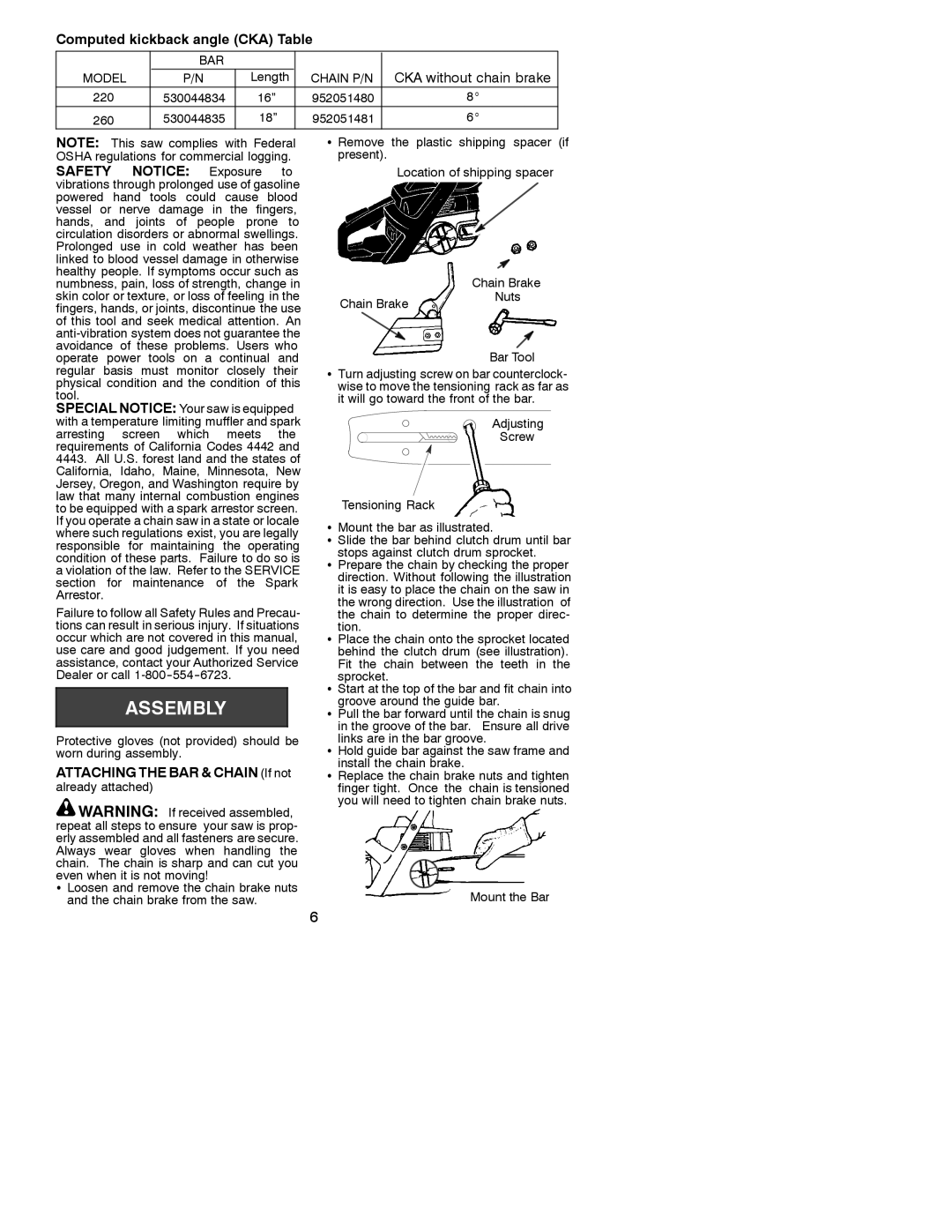
S Remove the plastic shipping spacer (if present).
Location of shipping spacer
|
|
|
|
|
|
|
|
|
| Chain Brake | |||
Chain Brake | Nuts | ||||||||||||
|
|
|
| ||||||||||
|
|
|
|
|
|
|
|
|
|
|
|
|
|
|
|
|
|
|
|
|
|
|
|
|
|
|
|
|
|
|
|
|
|
|
|
|
|
|
|
|
|
|
|
|
|
|
|
|
|
|
|
|
|
|
|
|
|
|
|
|
|
|
|
|
| Bar Tool | |||
STurn adjusting screw on bar counterclock- wise to move the tensioning rack as far as it will go toward the front of the bar.
Adjusting
Screw
Tensioning Rack
SMount the bar as illustrated.
SSlide the bar behind clutch drum until bar stops against clutch drum sprocket.
SPrepare the chain by checking the proper direction. Without following the illustration it is easy to place the chain on the saw in the wrong direction. Use the illustration of the chain to determine the proper direc-
tion.
SPlace the chain onto the sprocket located behind the clutch drum (see illustration). Fit the chain between the teeth in the
sprocket.
SStart at the top of the bar and fit chain into groove around the guide bar.
SPull the bar forward until the chain is snug in the groove of the bar. Ensure all drive links are in the bar groove.
SHold guide bar against the saw frame and install the chain brake.
SReplace the chain brake nuts and tighten finger tight. Once the chain is tensioned you will need to tighten chain brake nuts.
Mount the Bar
6