Assembly
Tools required for assembly:
Forklift or hoist with straps
(NOTE: A socket wrench set may speed assembly time)
Remove all crating and plastic from around the band saw. Remove any lag screws or holding straps which secure the band saw to the wood pallet.
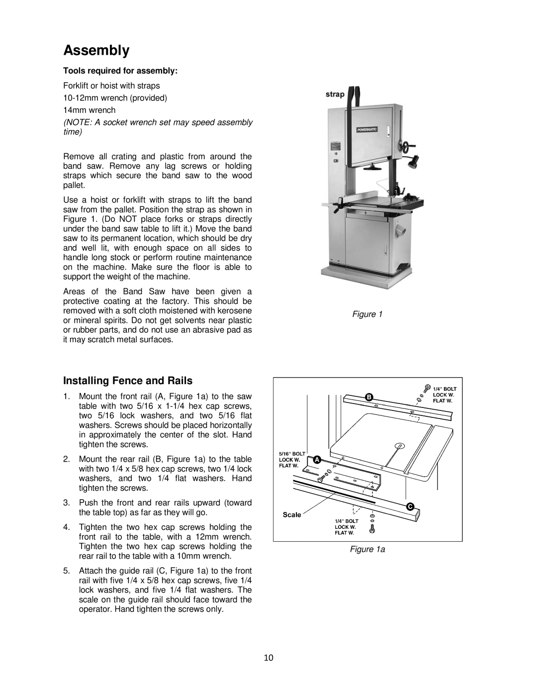
Use a hoist or forklift with straps to lift the band saw from the pallet. Position the strap as shown in Figure 1. (Do NOT place forks or straps directly under the band saw table to lift it.) Move the band saw to its permanent location, which should be dry and well lit, with enough space on all sides to handle long stock or perform routine maintenance on the machine. Make sure the floor is able to support the weight of the machine.
Areas of the Band Saw have been given a protective coating at the factory. This should be removed with a soft cloth moistened with kerosene or mineral spirits. Do not get solvents near plastic or rubber parts, and do not use an abrasive pad as it may scratch metal surfaces.
Installing Fence and Rails
1.Mount the front rail (A, Figure 1a) to the saw table with two 5/16 x
2.Mount the rear rail (B, Figure 1a) to the table with two 1/4 x 5/8 hex cap screws, two 1/4 lock washers, and two 1/4 flat washers. Hand tighten the screws.
3.Push the front and rear rails upward (toward the table top) as far as they will go.
4.Tighten the two hex cap screws holding the front rail to the table, with a 12mm wrench. Tighten the two hex cap screws holding the rear rail to the table with a 10mm wrench.
5.Attach the guide rail (C, Figure 1a) to the front rail with five 1/4 x 5/8 hex cap screws, five 1/4 lock washers, and five 1/4 flat washers. The scale on the guide rail should face toward the operator. Hand tighten the screws only.
10
Figure 1
Figure 1a