32 | Assembling and Maintaining RBK |
Connecting Cables (P20)
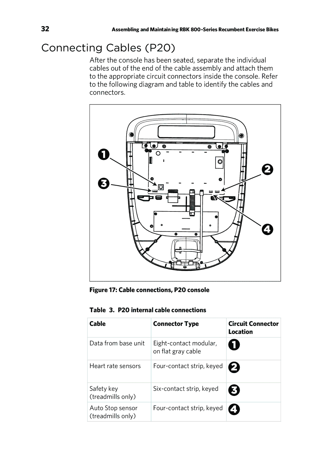
After the console has been seated, separate the individual cables out of the end of the cable assembly and attach them to the appropriate circuit connectors inside the console. Refer to the following diagram and table to identify the cables and connectors.
Figure 17: Cable connections, P20 console
Table 3. P20 internal cable connections
Cable | Connector Type | Circuit Connector |
|
| Location |
Data from base unit |
| |
| on flat gray cable |
|
Heart rate sensors |
| |
Safety key |
| |
(treadmills only) |
|
|
Auto Stop sensor |
| |
(treadmills only) |
|
|