Pressure Systems 9016 Finding Pin 1 on a PC BoardFigure 9a, Top Plate to P1 Connection on PC-322

Models: 9016

1 13
Download 13 pages 44.31 Kb
Page 10
Image 10

Pressure Systems, Inc.

9016 Upgrade Instructions

wire wrap, starting near the P6 connector. The freed white nylon spiral wire wrap may be re-used on other wires or tubes, or may simply be cut off and discarded. If you choose to cut off the spiral wire wrap, be careful not to nick or cut any other wires or tubes.

(3)Attach the wiring harnesses to their respective connectors, P1, P3, and P6. Note that the connector from P3 connects to your new PC-327 board. It will be connected to the PC-327 board after the PC-322/323 boards have been attached to the module top plate. Remember, the red line on your ribbon cable is to be connected to Pin 1 of the PCB.

(4)Plug the connector from the top plate into P1 of the PC-322 board. Be careful to connect the correct pins together (Pin1 to Pin1) and make sure the pins are aligned. If not, the PCB could be damaged. Pin 1 is denoted by the square pad on the solder side of the board. (See Figures 9, 9a, and 10.)

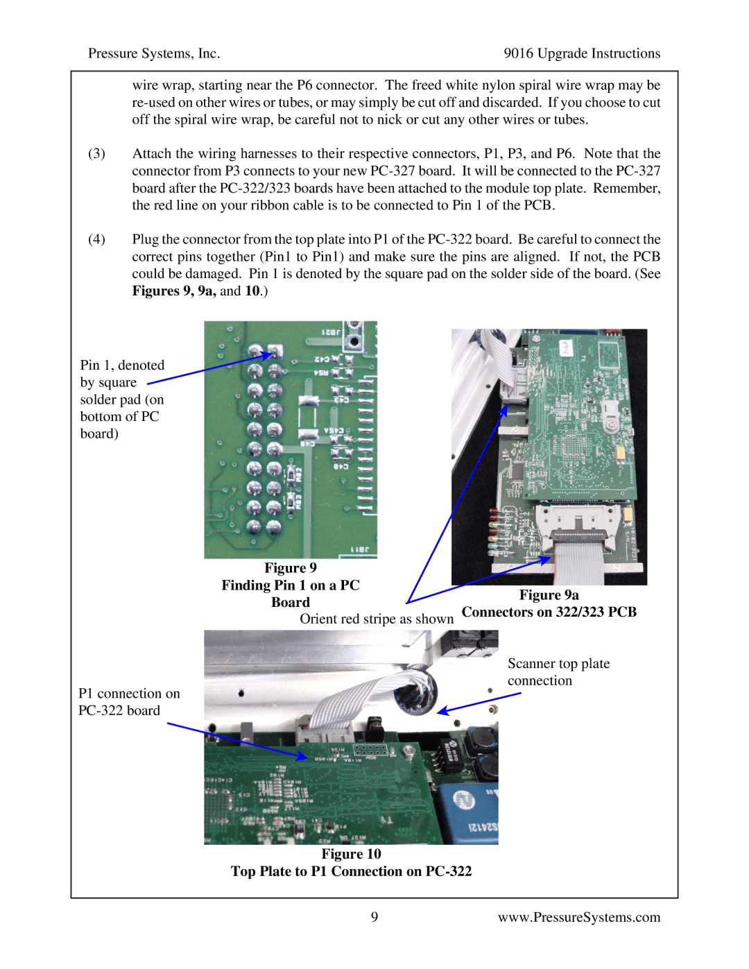
Pin 1, denoted by square solder pad (on bottom of PC board)

Figure 9

Finding Pin 1 on a PC

BoardFigure 9a

Orient red stripe as shown Connectors on 322/323 PCB

P1 connection on PC-322 board

Scanner top plate connection

Figure 10

Top Plate to P1 Connection on PC-322

9www.PressureSystems.com

Page 10
Image 10
Pressure Systems 9016 manual Finding Pin 1 on a PC BoardFigure 9a, Top Plate to P1 Connection on PC-322